Expanding Heatwave
8.1 Expanding the Heatwave® System
The following sections cover special considerations when using multiple Heatwave Mats and/or cables for expanding overall coverage of the system. All other installation instructions remain the same. Failure to follow the complete installation instructions can result in voiding your warranty, and permanent damage to your system.
All applicable tests should be performed on EACH Heatwave system independently to ensure proper operation of EACH unit connected to the complete system. Should you have more questions related to installing multiple Heatwave systems on one thermostat or a thermostat and power module, please contact Heatizon Systems at 888.239.1232, Monday through Friday, 8 am to 5 pm (MST), or email info@heatizon.com.
8.2 Purchase Heatwave® Expansion Components
Individual Heatwave® Cables or Mats are available for purchase outlined below:
- Contact the distributor that you purchased your Heatwave® system from.
- Visit heatizon.com/heatwave to explore various options for purchasing additional Cables, Mats,
power modules, thermostats, etc.
Individual components of the Heatwave system are not available on Amazon.
8.3 Planning the Expansion Installation
Before laying the Heatwave® Cable or Mat Floor Warming System, review the installation layout and verify that all dimensions match the need of the project. The installation plan should include the following:
- Placement, direction, and dimensions of the Heatwave® Cables or Mats.
- The starting and ending points of each Heating Cables length or Mats size.
- The location of the thermostat and/or power module or load switching relay.
- The location of the floor sensor between two heating cables.
REMEMBER! The installation plan for each area should be attached to this manual and be provided
to the building owner when the installation is complete.
8.4 Thermostat Models
The Heatwave® Cable or Mat Floor Warming System can use different thermostats to control the system. Below is a list of compatible thermostats with the power module, the Heatizon part number, and associated features.
| PART NUMBER | FEATURES |
|---|---|
| M429-PM | Power module for adding an extra circuit to a Heatwave system, to be controlled by an M429 line thermostat, with GFCI. |
| M429-NP | Non-programmable thermostat, temperature adjustment, floor sensor capable, GFCI, on/off. |
| M429 | Programmable, with 3 different schedules, 4 daily events, floor sensor capable, temperature adjustment, GFCI, on/off. |
| M429-TS | Same as M429, but touch-screen interface. |
| M429-WIFI | Same as M429-TS, but WIFI connection that enables thermostat to be control via an app. |
8.5 Heatwave® Multiple Units Scenarios
The following sections are for addressing planning and installation issues that come from installing multiple Heatwave® systems (cables or mats). There are two main expansion methods covered:
- Multiple Systems, Single Circuit (15 Amps)
Multiple Heatwave® Cables or Mats that do NOT exceed 15 amps, that are powered by a single thermostat. - Multiple Systems, Two Circuits (30 Amps)
Multiple Heatwave® Cables or Mats that do NOT exceed 30 amps, using two circuits, and a power module (M429-PM) that are controlled by a single thermostat. - Multiple Systems, One or More Circuits (20 Amps+)
In the instance where complete systems go over two circuits (30 amps total), or need to use breakers larger than 15 amps, contact Heatizon Systems (888-239-1232) directly for solutions for these applications.
8.6 Using the Expanded System
If all the instructions were followed when installing these systems, the thermostat will control all units attached to both the thermostat and the connected power module. There is no difference for programming or use of the system when multiple units are connected.

Follow local codes according to whether or not the Heatwave® system can be installed on a shared or dedicated breaker. Best practice is to keep the Heatwave® system on it’s own circuit breaker for optimal results, performance, and safety. When expanding the Heatwave® system, the system SHOULD be on a dedicated circuit.
8.7 Determining Heatwave® Total System Size
- Determine total square footage of area(s) to be heated.
- Use the following guidelines to determine system voltage and number of circuits:
- Single Circuit Systems (15A):
120v Mats: Maximum of 150 square feet of coverage.
240v Mats: Maximum of 300 square feet of coverage.
120v Cables: Range between
114(15w per SQFT)-214(8w per SQFT) square feet of coverage.
240v Cables: Range between
242(15w per SQFT)-453(8w per SQFT) square feet of coverage. - Double Circuit Systems (2x15A):
120v Mats: Maximum of 300 square feet of coverage.
240v Mats: Maximum of 600 square feet of coverage.
120v Cables: Range between
228(15w per SQFT)-428(8w per SQFT) square feet of coverage.
240v Cables: Range between
484(15w per SQFT)-906(8w per SQFT) square feet of coverage.
- Single Circuit Systems (15A):
- Plan breakup of mats and cables*.
If the area to be heated is continuous, choosing the products is as easy as dividing the area
between the available mats/cables until the desired size is reached, for example:
| 120v Mats Single Circuit | 120v Mats Double Circuit | 240v Mats Single Circuit | 240v Mats Double Circuit | 120v Cables Single Circuit | 120v Cables Double Circuit | 240v Cables Single Circuit | 240v Cables Double Circuit | ||
|---|---|---|---|---|---|---|---|---|---|
| SQFT: | 135 | 275 | 270 | 505 | 125 | 338 | 255 | 560 | |
| SYS 1 | HW2012- 1000 | HW2012- 1000 | HW2012- 1600B | HW2012- 1600B | HWC- 64120 | HWC- 64120 | HWC- 128239B | HWC- 114214B | |
| SYS 2 | HW2012- 350 | HW2012- 400 | HW2012- 1100B | HW2012- 1100B | HWC-815 | HWC-5094 | HWC- 3260B | HWC- 56105B | |
| SYS 3 | N/A | HW2012- 1000 | N/A | HW2012- 1450B | N/A | HWC- 64120 | N/A | HWC- 128239B | |
| SYS 4 | N/A | HW2012- 350 | N/A | HW2012- 900B | N/A | HWC-1630 | N/A | HWC- 3260B |
*Actual Size of combined systems may vary and be accomplished with different combinations.
Do NOT exceed 15 amps on either the thermostat (any model) or the power module. This will damage the unit and void your warranty.
- Combining of Heatwave® Mats and Cables is permissible if this is the best solution to your specific application. If installing differing systems, spacing for the free-roll cable must match to the spacing in the mat it is being paired with to ensure the same amount of heat output.
- When installing multiple Heatwave Cables, similar spacing should be followed across all the units to ensure matching heat output across the whole system.
In the event the combined systems are located in two separated areas, choose two systems that best match the square footage of the separate areas. Ensure that the total amperage per circuit is UNDER 15 amps, by using the charts below.
Heatwave® Mats,
12 Watts/Ft2, 120 VAC
| Heatizon Part Number | Amp Load | Coverage Area/Square Foot |
|---|---|---|
| HW2012-100 | 1.0 | 10 |
| HW2012-150 | 1.5 | 15 |
| HW2012-200 | 2.0 | 20 |
| HW2012-250 | 2.5 | 25 |
| HW2012-300 | 3.0 | 30 |
| HW2012-350 | 3.5 | 35 |
| HW2012-400 | 4.0 | 40 |
| HW2012-500 | 5.0 | 50 |
| HW2012-600 | 6.0 | 60 |
| HW2012-700 | 7.0 | 70 |
| HW2012-800 | 8.0 | 80 |
| HW2012-900 | 9.0 | 90 |
| HW2012-1000 | 10.0 | 100 |
Heatwave® Mats,
12 Watts/Ft2, 240 VAC
| Heatizon Part Number | Amp Load | Coverage Area/Square Foot |
|---|---|---|
| HW2012-400B | 2.0 | 40 |
| HW2012-500B | 2.5 | 50 |
| HW2012-600B | 3.0 | 60 |
| HW2012-700B | 3.5 | 70 |
| HW2012-800B | 4.0 | 80 |
| HW2012-900B | 4.5 | 90 |
| HW2012-1000B | 5.0 | 100 |
| HW2012-1100B | 5.5 | 110 |
| HW2012-1200B | 6.0 | 120 |
| HW2012-1450B | 7.3 | 145 |
| HW2012-1600B | 8.0 | 160 |
Heatwave® Cables,
120/240 VAC
| Heatizon Part Number 120V Input | ||
|---|---|---|
| HWC-815 | 1.0 | 8-15 |
| HWC-1630 | 2.0 | 16-30 |
| HWC-3260 | 4.0 | 32-60 |
| HWC-5094 | 6.3 | 50-94 |
| HWC-64120 | 8.0 | 64-120 |
| 240V Input | ||
| HWC-1631B | 1.0 | 16-31 |
| HWC-3260B | 2.0 | 32-60 |
| HWC-56105B | 3.5 | 56-105 |
| HWC-80150B | 5.0 | 80-150 |
| HWC-114214B | 7.0 | 114-214 |
| HWC-128239B | 8.0 | 128-239 |
Do NOT mix voltages when combining systems. 120 volt systems MUST only be paired with other 120 volt systems. 240 volt systems are denoted by a “B” at the end of the Heatizon part number.
8.7.1 CALCULATE YOUR AMP LOADS – DO NOT EXCEED 15 AMPS!
In any application of a Heatwave system involving a Power Module, If a floor sensor is being used, it is connected to the thermostat. More information about installing the floor sensor.
8.8 Expansion Layout Design
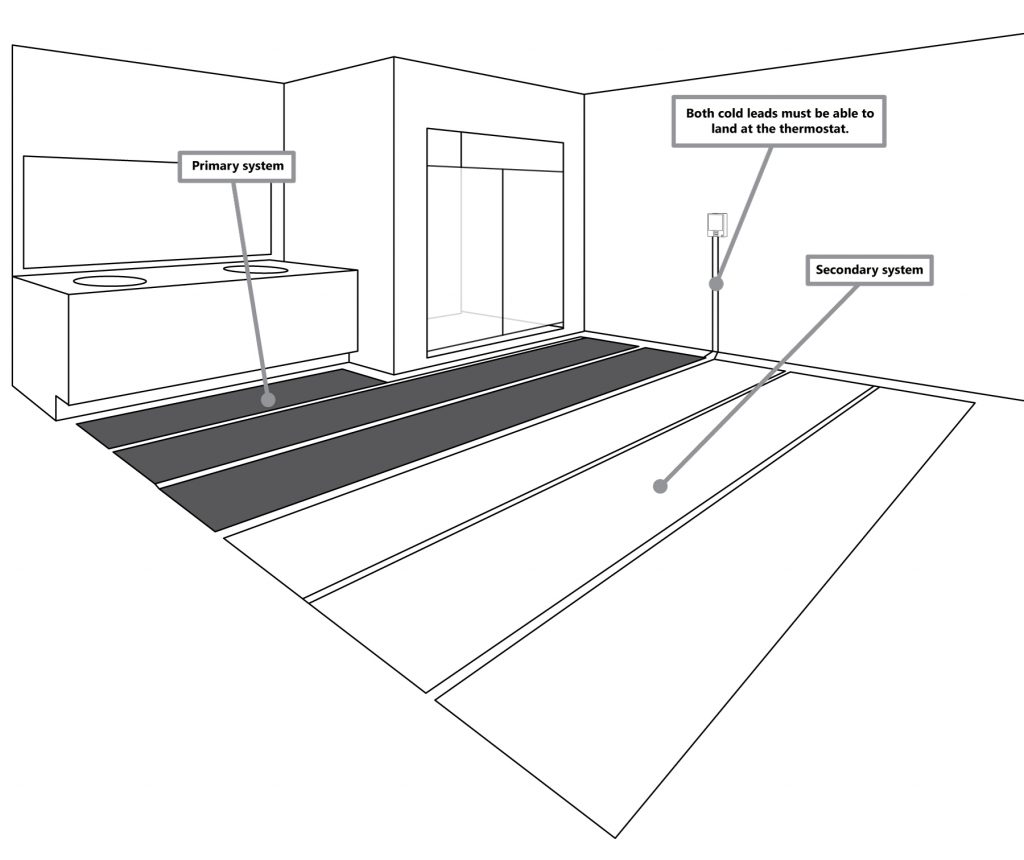
8.8.1 Option 1: Multiple Systems On One Thermostat (Single Circuit)
After you have measured your space(s), and determined which systems you will use, locating the thermostat is important. The systems cold lead’s must be able to be terminated at the thermostat in order to be controlled simultaneously. The diagram below gives an example of how two systems should be laid out.
If there are two separate spaces to be heated, the thermostat should be located on a shared wall
where cold leads can be connected at the thermostat.
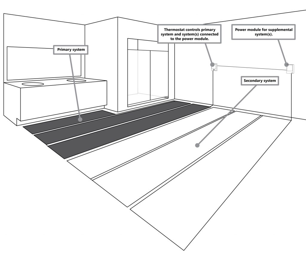
8.8.2 Option 2: Multiple Systems Using A Thermostat & Power Module (Double Circuit)
If the desired method is to use multiple Heatwave systems with a thermostat and a power module, determine which systems will be connected to which unit ensuring that neither system exceeds 15 amps. In this method, the cold leads must be able to reach the designated unit in order to work properly. The diagram below shows an example of how this can be accomplished. The power module is connected to the thermostat via a wired connection. Therefore, as long as the thermostat and power module can be connected via this wire, the location of the power module has no location restrictions outside of local codes. The power module uses a standard single-gang electrical box for wall installation.
- Do NOT exceed 15 amps for either the thermostat or power module.
- Failure to connect the power module to the thermostat will result in any systems connected to the power module to be non-functional.
8.9 Wiring Expansion Systems
8.9.1 Multiple Systems On One Thermostat (Single Circuit)
See the following diagram about how to wire multiple systems to a single thermostat or power module.
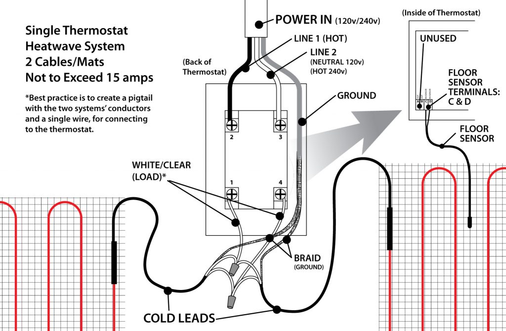
- Do not run floor sensor wire in the same conduit as the cold lead(s), or connect them in anyway. There is a chance that electronic interference can cause issues with getting accurate readings from the floor sensor.
- In the event that there is interest in adding more than one power module (more than two circuits), please contact Heatizon Systems (888.239.1232), for specific installation instructions for this application.
- Best Practice is to create two pigtails, each with a conductor (from the cold lead) and a segment of wire, which is connected to the thermostat, reducing the amount of wires physically connected to the thermostat. Check local codes for further information.
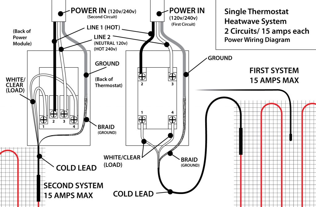
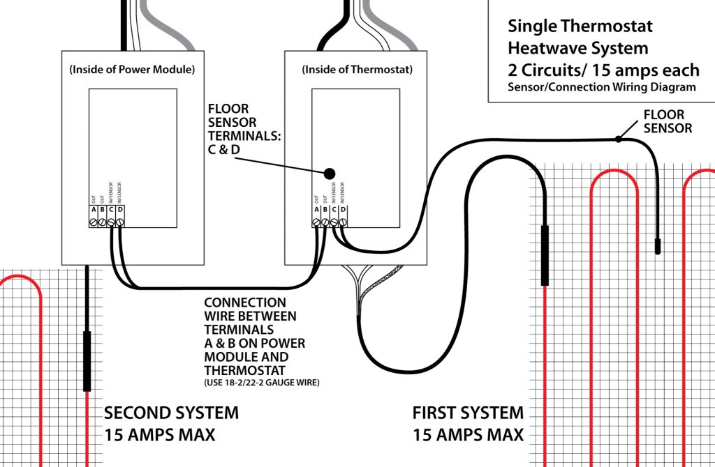
8.9.2 Multiple Systems Using A Thermostat & Power Module (Double Circuit)
See the following diagrams about how to wire multiple systems to a thermostat and a power module.