Installation Basics
Follow these steps to ensure a successful Heatwave® installation.
5.1.1 PLAN THE LAYOUT
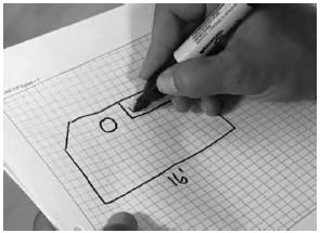
Make a sketch layout or a floor plan of the room; include all permanent furnishings such as toilets, bathtubs, appliances, cabinetry, etc. Indicate all dimensions required to determine the available floor area and the position of the thermostat.
Heatizon recommends that the installation be documented with photos and drawings to note the location of connections and the sensor, as well as the cable layout.

Important: Mark the position of the connection point between the power lead and the red Heatwave® heating cable. This connection must be embedded in cementitious material. When using a floor temperature sensing thermostat, mark the sensor position in the middle of two heating cables, about 10 in. (25 cm) away from the wall (within the heated area), as close as possible to the thermostat.
5.1.2 TRANSFER LAYOUT TO FLOOR
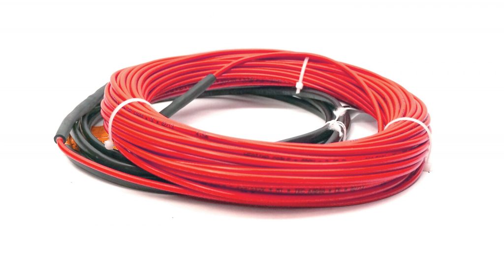
Draw an outline of the layout on the room floor including a foot print of all furnishings that are not yet installed. Unroll the first few feet of the Heatwave® Mat or Cable. The starting point of the cable must be placed within 15ft. of the thermostat.
5.1.3 INSTALL SENSOR
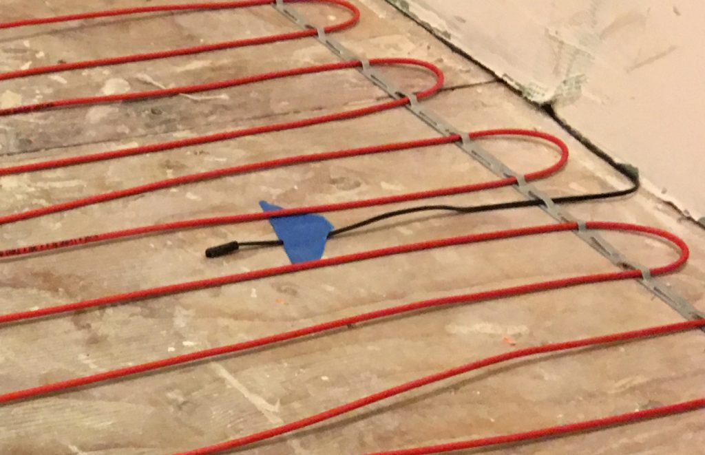
If using a floor temperature sensing thermostat, install the sensor now, either in conduit tube, or directly to the subfloor. The sensor and/or tube needs to be installed between the thermostat wall box and the sensor position. The conduit tube must be partially countersunk into the subfloor. Cut a channel in the floor to a location below the thermostat for the sensor conduit. The conduit has to go from the wall below the thermostat and minimum of 10” away from the wall towards the middle of the floor for placement between two runs of cable.
5.1.4 PREPARE SUBFLOOR SURFACE
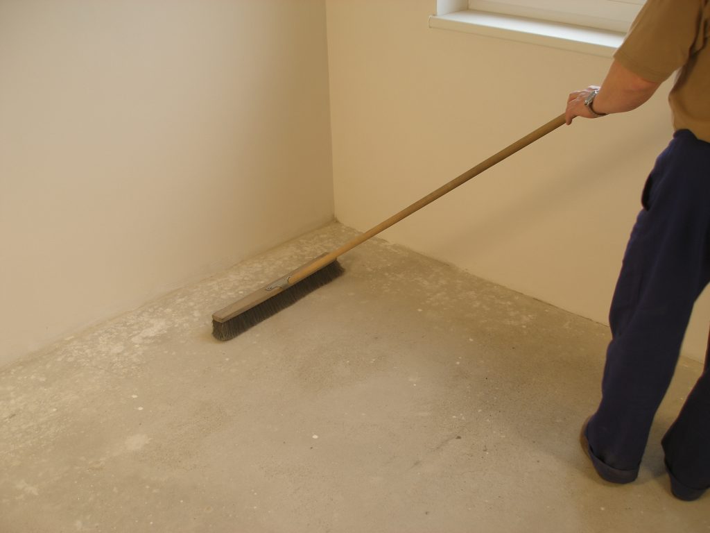
Clean and vacuum the floor thoroughly and remove dust and debris from the floor that may damage the heating cable. Ensure that the subfloor is secure and stable. Carefully fill in all cracks to prevent any potential damage to the new tiles resulting from shifts in the subfloor.
5.1.5 MEASURE THE RESISTANCE (TEST #1)
Use a digital Ohm meter to measure the resistance of the Heatwave® Mat/Cable and compare it to the total Ohms in the tables in Section 4.1 for Mats or in Section 4.2 for Cables. Record the measured resistance on the Registration Form. Documenting the resistance at each stage of installation is required for warranty purposes. Also, measure the resistance between each conductor and the shielding/ground wire. Both should read infinity or open. Please refer to Section 7 (Commissioning) for instructions on how to measure the resistance.
NEVER CUT OR SHORTEN THE RED HEATING CABLE!
DO NOT STAPLE THE RED HEATWAVE® HEATING CABLE. STAPLE ONLY THE WEBBING ON HEATWAVE® MATS WHERE NO CABLE IS LOCATED!
NEVER PLACE RED CABLE WITHIN 6” OF A WAX TOILET RING.
Install
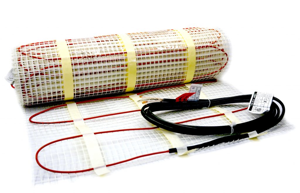
HEATWAVE® MATS
Install
HEATWAVE® CABLES