Commissioning
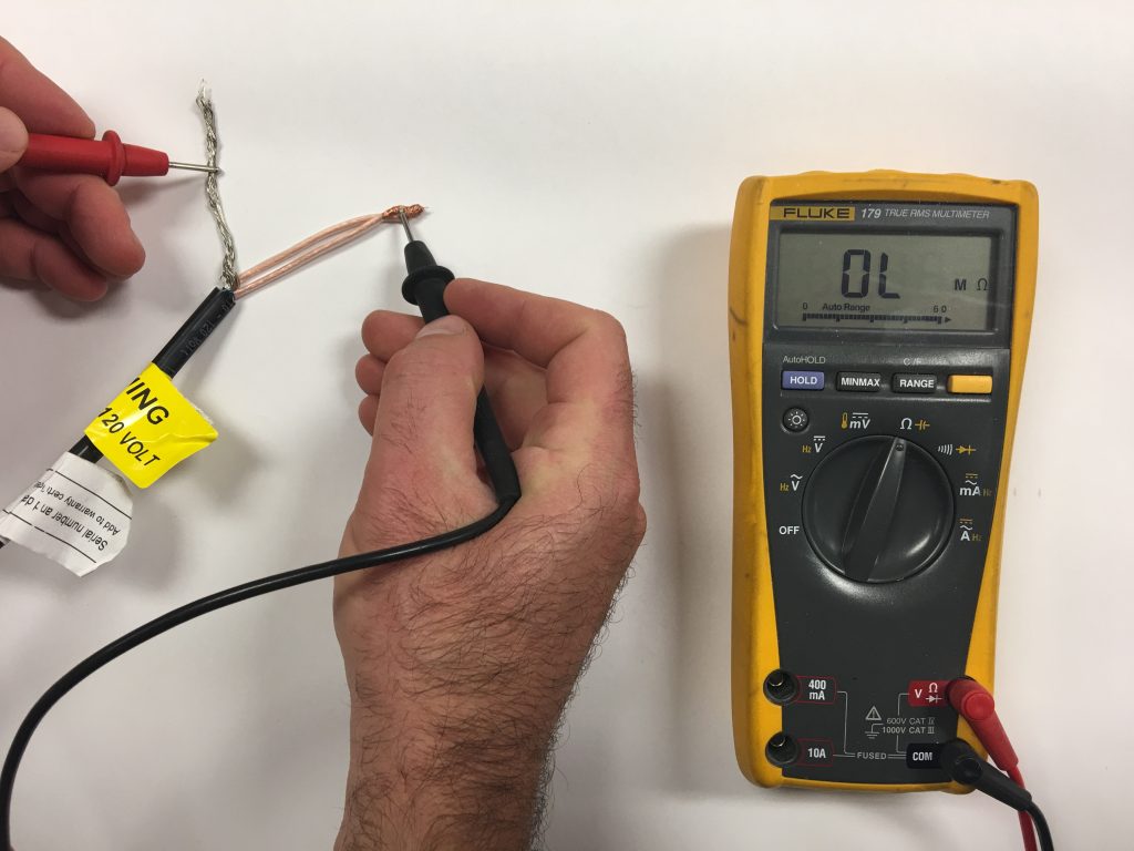
7.1 INSULATION RESISTANCE TEST
This test ensures that the insulating jackets of the heating cable are not damaged. A low value indicates the cable has been damaged and must be replaced.
- Set the multimeter to 2000K ohm.
- Connect* the ground wire to the black lead and both white conductors to the red lead of the multimeter.
- Make sure the meter indicates, “Open,” “OL,” “1,” or infinity. If there is a different reading, contact Heatizon at 888-239-1232.
- Record these readings on the Registration Form.
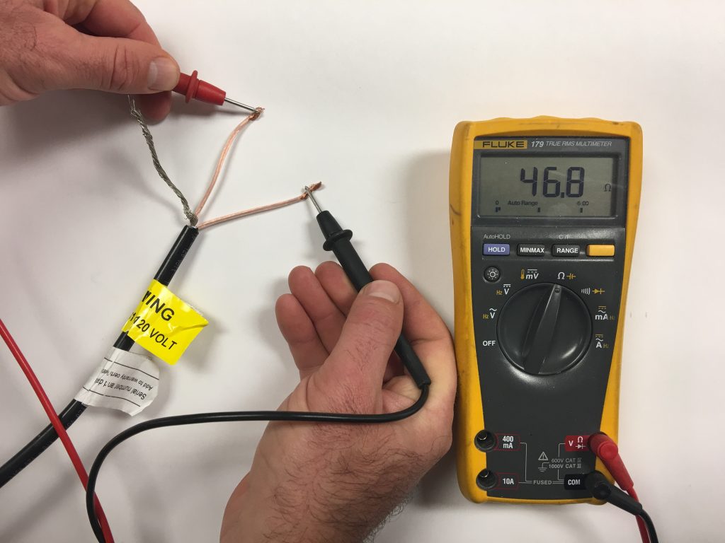
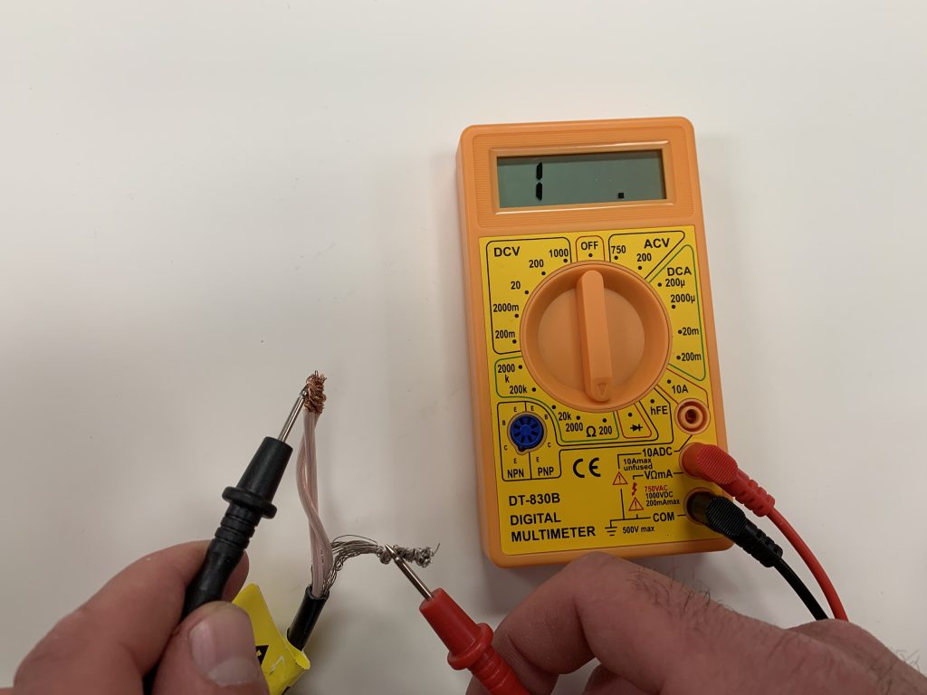
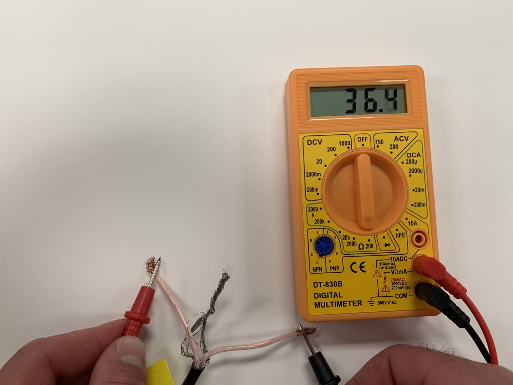
7.2 HEATING CABLE RESISTANCE TEST
This test measures the resistance of the Heatwave® Mat or Cable, and is used to determine circuit integrity.
- Set the multimeter to the 200 or 2000 ohm range.
- Connect* the multimeter leads, one to each white conductor on the cold lead.
- Compare this resistance reading to the resistance specified in the tables in Section 4.1 or 4.2. The value should be within ±10%. If there is a different reading than expected, contact Heatizon at 888-239-1232.
- Record these readings on the Registration Form.
7.3 SENSOR RESISTANCE TEST
This test measures the resistance of the floor sensor and is used to verify the sensor integrity.
- Set the multimeter to the 200K ohm range.
- Connect* the multimeter leads to each sensor lead wire.
- Make sure the meter reads between 9-25K ohms.
- If there is a different reading, contact Heatizon at 888-239-1232.
* Be sure when connecting the multimeter to the leads, do not touch the connection with bare hands or that two connections do not touch.
7.4 USING A FLOOR ALARM/SCREAMER
If a floor alarm/screamer unit is being used that was part of the Heatwave® Premium Kits or purchased separately, follow the following instructions for use.
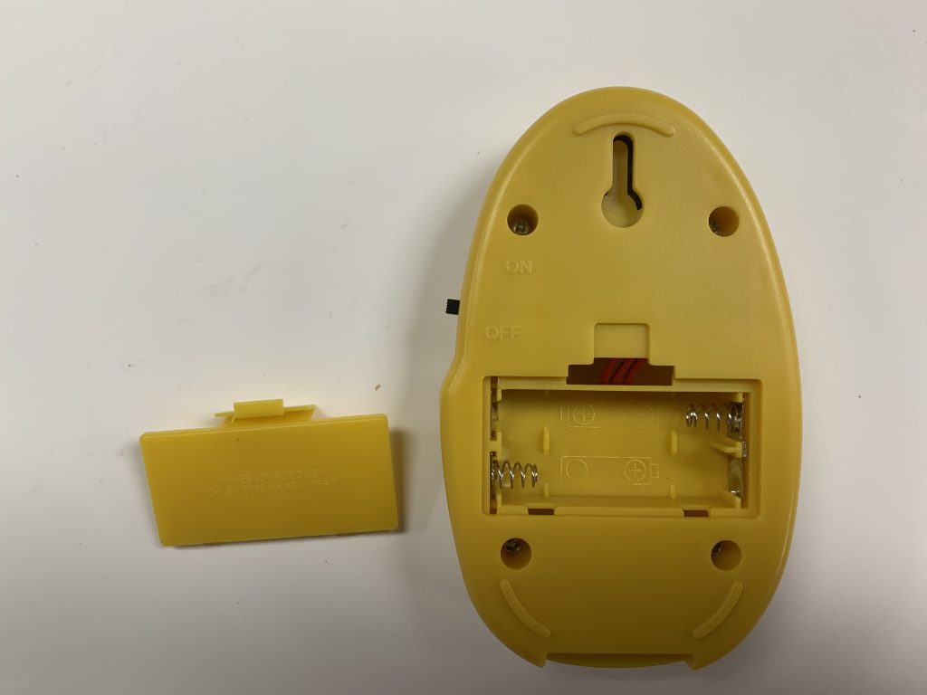
- Install two AAA batteries (included with Premium Kits) by removing compartment on the backside of the device, close the compartment.
- Switch the power on to the unit using the power switch, the device alarm should sound, also the power and alarm lights should illuminate. If the unit does not power on correctly, check to see if batteries are installed properly. Power the unit off.
- Be sure the cold lead has been ran into the connection box/thermostat location, BEFORE beginning the layout of the Heatwave® cable or mat.
- Connect the two copper wires with clear/white sheath to the terminals marked “L1” and “L2” on the floor alarm, using the screwdriver supplied, making sure the terminals are tightly screwed down.
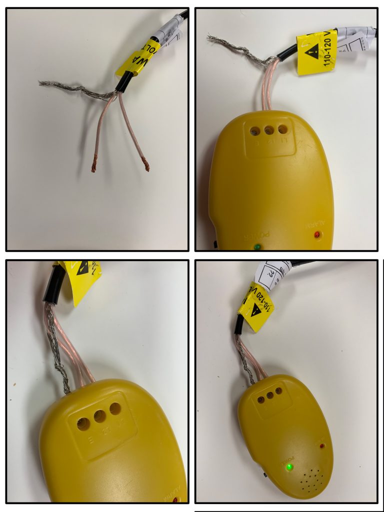
- Twist the silver ground wire tight and connect to the terminal marked “E/G,” again ensure the terminal is screwed down tight.
- Power on the unit, the device should NOT make a sound and only the POWER light should illuminate, if the ALARM light is lit and the alarm sounds, turn it off and check the connections and power the unit back on.
- Leave the floor alarm connected* and powered on whenever working on the Heatwave® system until it has been fully installed and flooring is complete, remove only when the system needs to be connected to the thermostat.
*Only disconnect the floor alarm when the manual requires the Heatwave system be tested using a multimeter, then reconnect after testing is complete. - After you have finished using the Floor Alarm you may visit Heatizon.com/alarmrecycle to recycle the alarm responsibly and free of charge.

WARNING: IF THE FLOOR ALARM SOUNDS DURING THE INSTALLATION OF THE HEATWAVE® SYSTEM, STOP AND CHECK GROUND AND RESISTANCE (SECTION 7.1 AND 7.2), IF THE RESULTS DO NOT MATCH TO THE CHARTS, THE SYSTEM IS DAMAGED. CONTACT HEATIZON SYSTEMS 1-888-239-1232 FOR FURTHER INSTRUCTIONS ON HOW TO PROCEED WITH A REPAIR.
The Floor Alarms are specifically designed to monitor floor heating systems only. Any use outside of that for which they are specifically designed, is not recommended. Heatizon is committed to responsibly recycling/disposing of these units free of charge. Visit Heatizon.com/alarmrecycle for more information.

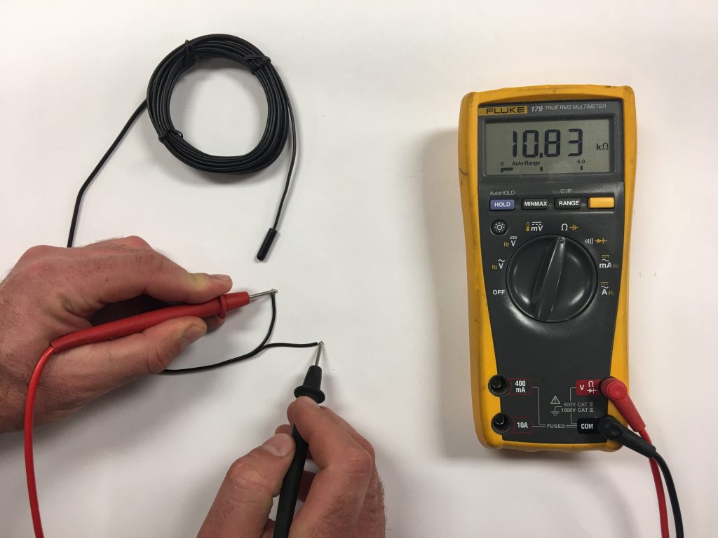
7.5 USING THE HEATIZON MULTIMETER
This multimeter is supplied with the Heatwave® Premium Kits or the Premium Add-on kit. This usage applies to testing the Heatwave® system only. For other uses/operations consult the devices manual*.
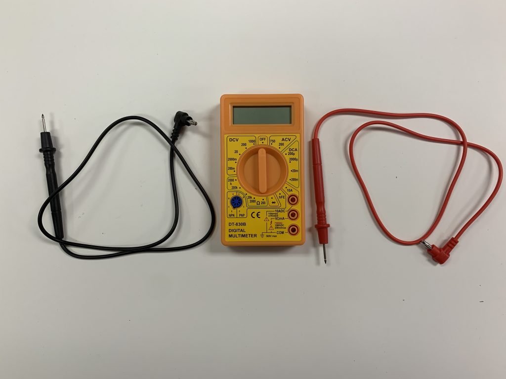
SETUP THE MULTIMETER:
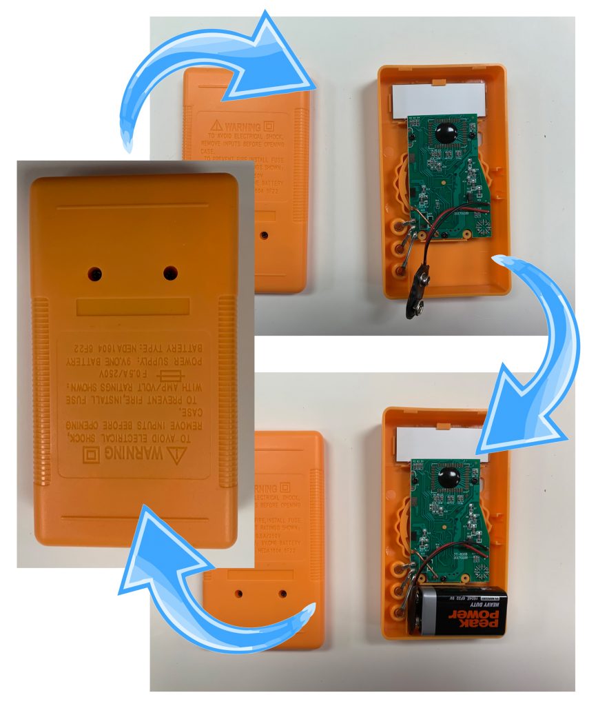
- Install the battery (supplied) by removing the two screws on the back of the meter, then plugging the battery into the terminal inside. Replace the back of the meter and screw it tight.
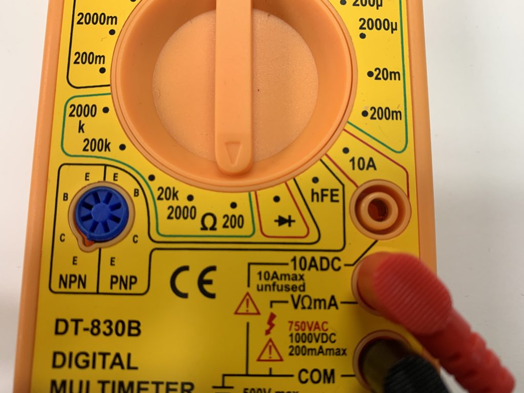
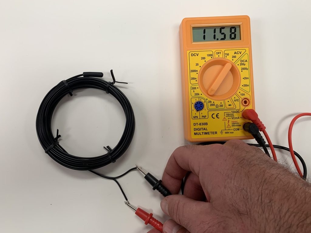
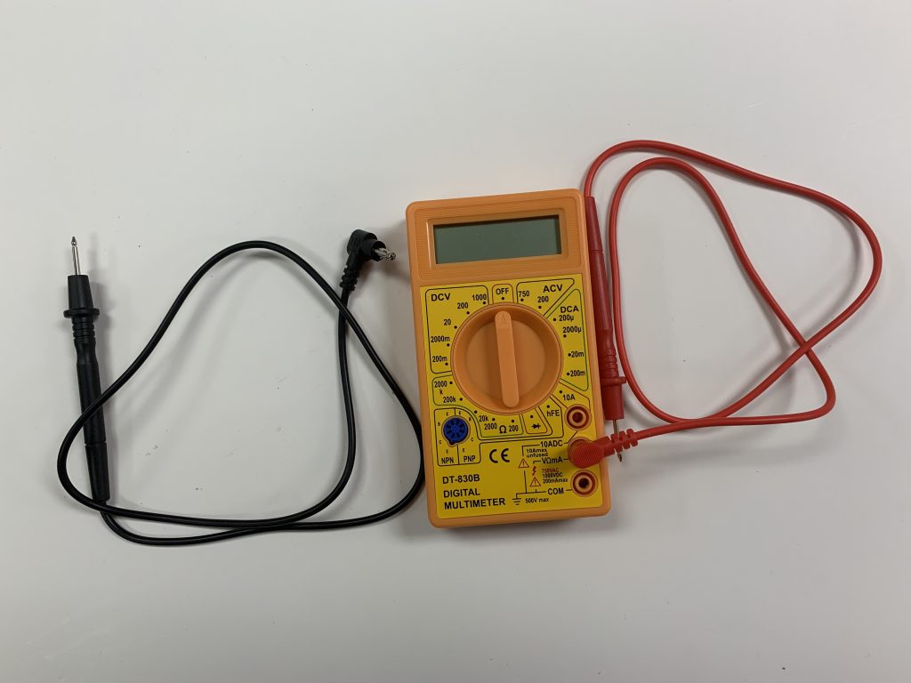
- Install the red lead on the middle port on the front of the meter.
- Install the black lead in the lower port on the front of the meter.
USING THE MULTIMETER:
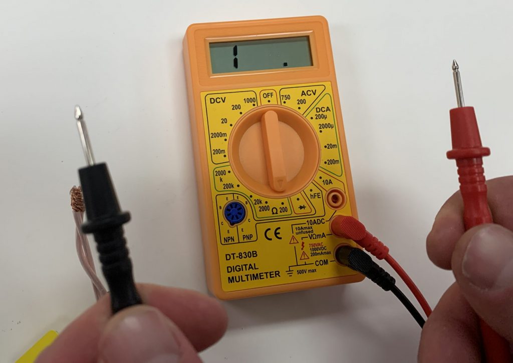
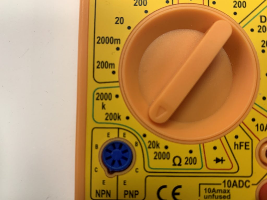
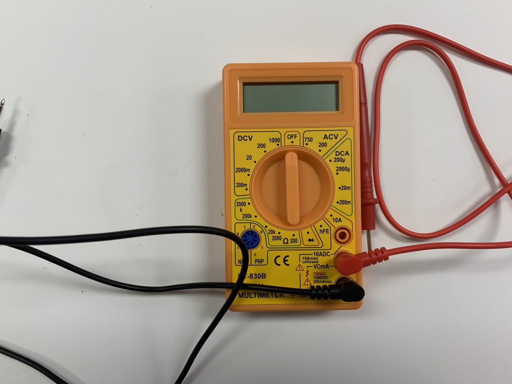
- For the INSULATION RESISTANCE TEST (7.1) rotate the dial should be set to 200 in the Ohms section (Denoted by the Ω symbol) (Image 7.5A). Ensure that the display reads “1,” to indicate an open circuit (Image 7.5B) then proceed with the instructions outlined in step 7.1.
- For the HEATING CABLE RESISTANCE TEST (7.2) keep the dial at the 200 ohms setting then proceed with the instructions outlined in step 7.2.
- For the SENSOR RESISTANCE TEST (7.3), rotate the dial to the 20k ohm setting (image 7.5C) then proceed with the instructions outlined in step 7.3.
*Heatizon offers no warranty or support for the multimeter outside of this tutorial.