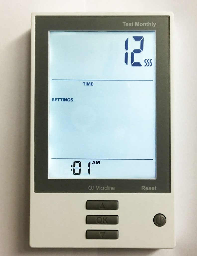
After the M429 GFCI Thermostat has been installed and powered on, there are a few settings to adjust in order to take full advantage of the Heatwave system. This is a quick start guide, for complete instructions, please consult the manual included with the thermostat.
Upon the first power-up the unit should automatically require setting the current time. Using the UP and DOWN arrow buttons adjust the hour to the current hour. Then press the OK button to move to the minutes, adjust minutes using the UP or DOWN buttons. Then press the OK button.
9.1.2 SETTING THE CURRENT DAY
After setting the time, there will be a prompting to choose the correct day of the week. Select the current day using the UP or DOWN buttons, then press the OK button. Then be returned to the main screen.
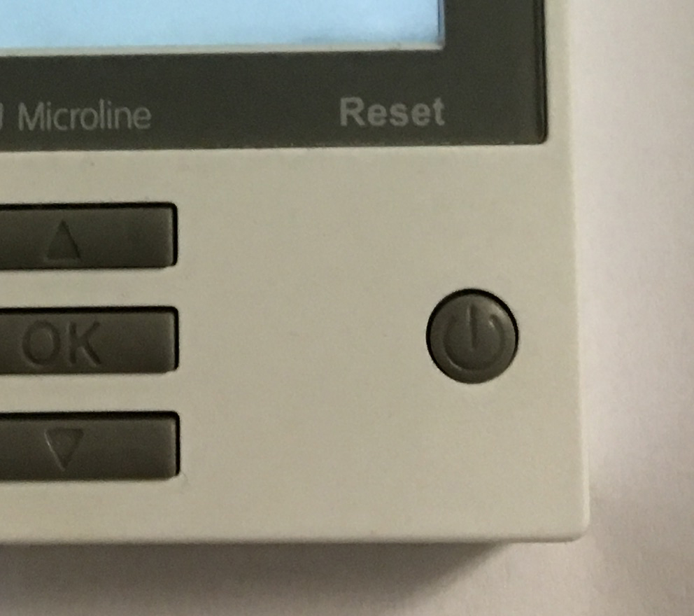
POWER BUTTON: Pressing this button once powers on the unit, holding it down for a few seconds turns it off. While not in Active Mode (no screen backlight), press the OK button twice to enter the menu.
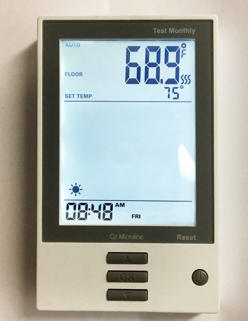
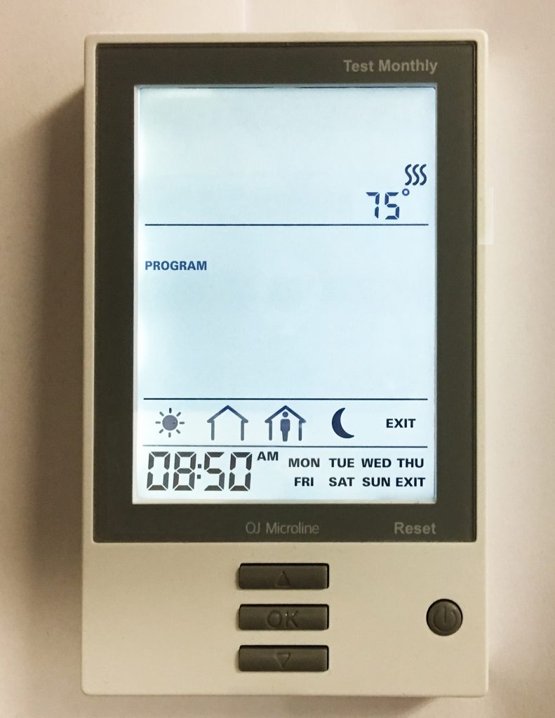
9.2 HOME SCREEN
This is the default screen for a powered on and partially setup unit.
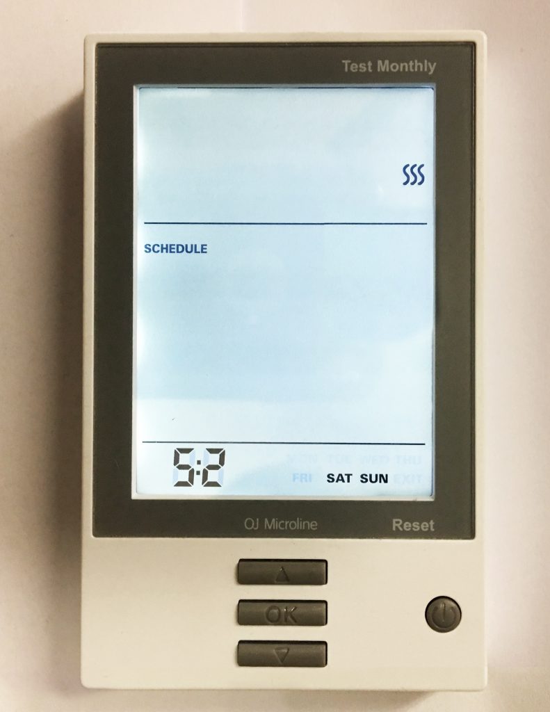
9.3 SCHEDULE SELECT
On the main menu, the second option down SCHEDULE (press OK to select the SCHEDULE settings, and OK again to edit these settings) is for determining whether the unit will run a program based on the following options:
7:0 – Runs the same temperature and time settings every day of the week.
6:1 – Six days of the week the temperature and time settings are the same, while Sunday is on a separate program.
5:2 – The program will run the same temperature and time Monday through Friday, but will run a separate program on Saturday and Sunday.
Using the UP or DOWN buttons select a desired schedule for the thermostat, then press the OK to confirm the choice.
9.4 PROGRAM SELECT
The third option down PROGRAM (press OK to select the PROGRAM settings, and OK again to edit these settings) is where the majority of thermostat programming takes place. All the programming in this function will be done using the UP, DOWN and OK buttons.
9.4.1 FIRST SELECTION:
Setting program based on preferred SCHEDULE settings (see section 8.4). This will either be one or two different programs. The first program will be blinking. To change the SCHEDULE to program, use the UP or DOWN buttons. Press the OK button to edit that program.
9.4.2 SECOND SELECTION:
Setting time period to be programmed. Using the UP or DOWN buttons to select one of the following, then pressing OK to edit:
MORNING (SUN)
DAY (AWAY/EMPTY HOUSE)
EVENING (HOME/FULL HOUSE)
NIGHT (MOON)
9.4.3 THIRD SELECTION:
This is where the exact activation time for the time period is set. Use the UP and DOWN buttons to adjust the time accordingly. Press OK once done.
(Time is adjusted in 15 minute increments. Only one exact time per period is available.)
9.4.4 FINAL SELECTION:
The last setting is where the desired temperature is selected. Using the UP and DOWN buttons select a temperature. Press OK to confirm the setting.
(The range is between 32° – 104° Fahrenheit, however the Heatwave system may not be able to heat to that same range based on several factors.)
Each time OK is pressed, the program, will automatically move to the program section. In the case where there are two schedules, once the final setting for the first schedule is finalized, hitting the OK button will move to the next schedule to program, if applicable.
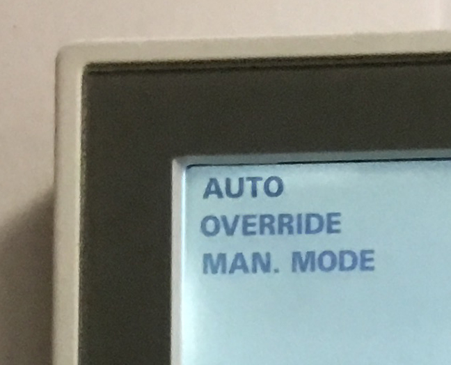
9.5 MODE SELECT
On the main screen, the MODE menu will be shown blinking first with three options:
AUTO – Default mode that most users will want to use which sets temperature based on a user-created schedule.
OVERRIDE – To temporarily override temperature/schedule settings.
MAN. MODE – To use the thermostat to adjust the temperature on user input without a schedule.
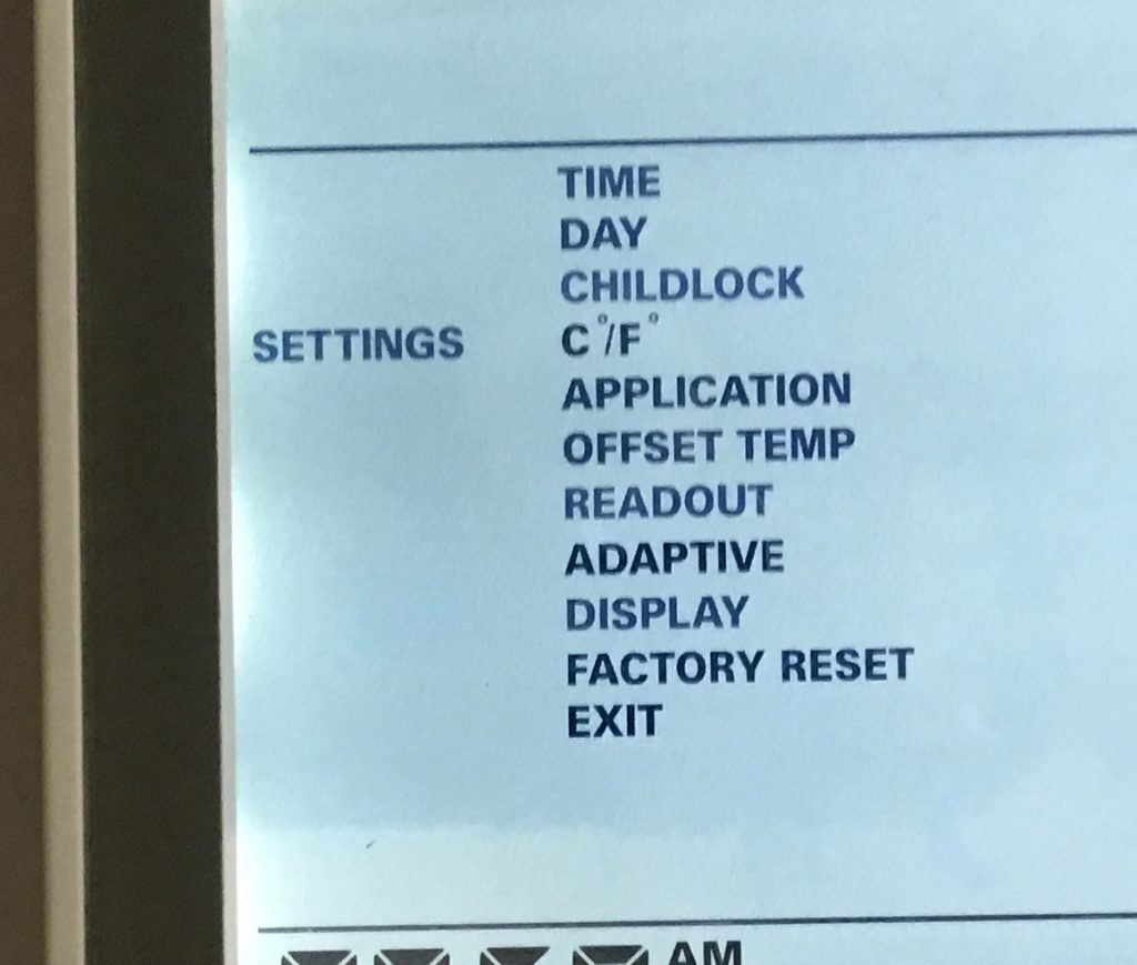
9.6 OTHER SETTINGS
SETTINGS (fourth menu item from the top) is where several other options can be configured for this thermostat. Please consult the user manual for complete information about these options.
The following sections cover special considerations when using multiple Heatwave Mats and/or cables for expanding overall coverage of the system. All other installation instructions remain the same. Failure to follow the complete installation instructions can result in voiding your warranty, and permanent damage to your system.
All applicable tests should be performed on EACH Heatwave system independently to ensure proper operation of EACH unit connected to the complete system. Should you have more questions related to installing multiple Heatwave systems on one thermostat or a thermostat and power module, please contact Heatizon Systems at 888.239.1232, Monday through Friday, 8 am to 5 pm (MST), or email info@heatizon.com.
8.2 Purchase Heatwave® Expansion Components
Individual Heatwave® Cables or Mats are available for purchase outlined below:
Contact the distributor that you purchased your Heatwave® system from.
Visit heatizon.com/heatwave to explore various options for purchasing additional Cables, Mats, power modules, thermostats, etc.
Individual components of the Heatwave system are not available on Amazon.
8.3 Planning the Expansion Installation
Before laying the Heatwave® Cable or Mat Floor Warming System, review the installation layout and verify that all dimensions match the need of the project. The installation plan should include the following:
Placement, direction, and dimensions of the Heatwave® Cables or Mats.
The starting and ending points of each Heating Cables length or Mats size.
The location of the thermostat and/or power module or load switching relay.
The location of the floor sensor between two heating cables.
REMEMBER! The installation plan for each area should be attached to this manual and be provided to the building owner when the installation is complete.
8.4 Thermostat Models
The Heatwave® Cable or Mat Floor Warming System can use different thermostats to control the system. Below is a list of compatible thermostats with the power module, the Heatizon part number, and associated features.
PART NUMBER
FEATURES
M429-PM
Power module for adding an extra circuit to a Heatwave system, to be controlled by an M429 line thermostat, with GFCI.
M429-NP
Non-programmable thermostat, temperature adjustment, floor sensor capable, GFCI, on/off.
M429
Programmable, with 3 different schedules, 4 daily events, floor sensor capable, temperature adjustment, GFCI, on/off.
M429-TS
Same as M429, but touch-screen interface.
M429-WIFI
Same as M429-TS, but WIFI connection that enables thermostat to be control via an app.
8.5 Heatwave® Multiple Units Scenarios
The following sections are for addressing planning and installation issues that come from installing multiple Heatwave® systems (cables or mats). There are two main expansion methods covered:
Multiple Systems, Single Circuit (15 Amps) Multiple Heatwave® Cables or Mats that do NOT exceed 15 amps, that are powered by a single thermostat.
Multiple Systems, Two Circuits (30 Amps) Multiple Heatwave® Cables or Mats that do NOT exceed 30 amps, using two circuits, and a power module (M429-PM) that are controlled by a single thermostat.
Multiple Systems, One or More Circuits (20 Amps+) In the instance where complete systems go over two circuits (30 amps total), or need to use breakers larger than 15 amps, contact Heatizon Systems (888-239-1232) directly for solutions for these applications.
8.6 Using the Expanded System
If all the instructions were followed when installing these systems, the thermostat will control all units attached to both the thermostat and the connected power module. There is no difference for programming or use of the system when multiple units are connected.
Follow local codes according to whether or not the Heatwave® system can be installed on a shared or dedicated breaker. Best practice is to keep the Heatwave® system on it’s own circuit breaker for optimal results, performance, and safety. When expanding the Heatwave® system, the system SHOULD be on a dedicated circuit.
8.7 Determining Heatwave® Total System Size
Determine total square footage of area(s) to be heated.
Use the following guidelines to determine system voltage and number of circuits:
Single Circuit Systems (15A): 120v Mats: Maximum of 150 square feet of coverage. 240v Mats: Maximum of 300 square feet of coverage. 120v Cables: Range between 114(15w per SQFT)-214(8w per SQFT) square feet of coverage. 240v Cables: Range between 242(15w per SQFT)-453(8w per SQFT) square feet of coverage.
Double Circuit Systems (2x15A): 120v Mats: Maximum of 300 square feet of coverage. 240v Mats: Maximum of 600 square feet of coverage. 120v Cables: Range between 228(15w per SQFT)-428(8w per SQFT) square feet of coverage. 240v Cables: Range between 484(15w per SQFT)-906(8w per SQFT) square feet of coverage.
Plan breakup of mats and cables*. If the area to be heated is continuous, choosing the products is as easy as dividing the area between the available mats/cables until the desired size is reached, for example:
120v Mats Single Circuit
120v Mats Double Circuit
240v Mats Single Circuit
240v Mats Double Circuit
120v Cables Single Circuit
120v Cables Double Circuit
240v Cables Single Circuit
240v Cables Double Circuit
SQFT:
135
275
270
505
125
338
255
560
SYS 1
HW2012- 1000
HW2012- 1000
HW2012- 1600B
HW2012- 1600B
HWC- 64120
HWC- 64120
HWC- 128239B
HWC- 114214B
SYS 2
HW2012- 350
HW2012- 400
HW2012- 1100B
HW2012- 1100B
HWC-815
HWC-5094
HWC- 3260B
HWC- 56105B
SYS 3
N/A
HW2012- 1000
N/A
HW2012- 1450B
N/A
HWC- 64120
N/A
HWC- 128239B
SYS 4
N/A
HW2012- 350
N/A
HW2012- 900B
N/A
HWC-1630
N/A
HWC- 3260B
*Actual Size of combined systems may vary and be accomplished with different combinations.
Do NOT exceed 15 amps on either the thermostat (any model) or the power module. This will damage the unit and void your warranty.
Combining of Heatwave® Mats and Cables is permissible if this is the best solution to your specific application. If installing differing systems, spacing for the free-roll cable must match to the spacing in the mat it is being paired with to ensure the same amount of heat output.
When installing multiple Heatwave Cables, similar spacing should be followed across all the units to ensure matching heat output across the whole system.
In the event the combined systems are located in two separated areas, choose two systems that best match the square footage of the separate areas. Ensure that the total amperage per circuit is UNDER 15 amps, by using the charts below.
Heatwave® Mats, 12 Watts/Ft2, 120 VAC
Heatizon Part Number
Amp Load
Coverage Area/Square Foot
HW2012-100
1.0
10
HW2012-150
1.5
15
HW2012-200
2.0
20
HW2012-250
2.5
25
HW2012-300
3.0
30
HW2012-350
3.5
35
HW2012-400
4.0
40
HW2012-500
5.0
50
HW2012-600
6.0
60
HW2012-700
7.0
70
HW2012-800
8.0
80
HW2012-900
9.0
90
HW2012-1000
10.0
100
Heatwave® Mats, 12 Watts/Ft2, 240 VAC
Heatizon Part Number
Amp Load
Coverage Area/Square Foot
HW2012-400B
2.0
40
HW2012-500B
2.5
50
HW2012-600B
3.0
60
HW2012-700B
3.5
70
HW2012-800B
4.0
80
HW2012-900B
4.5
90
HW2012-1000B
5.0
100
HW2012-1100B
5.5
110
HW2012-1200B
6.0
120
HW2012-1450B
7.3
145
HW2012-1600B
8.0
160
Heatwave® Cables, 120/240 VAC
Heatizon Part Number 120V Input
HWC-815
1.0
8-15
HWC-1630
2.0
16-30
HWC-3260
4.0
32-60
HWC-5094
6.3
50-94
HWC-64120
8.0
64-120
240V Input
HWC-1631B
1.0
16-31
HWC-3260B
2.0
32-60
HWC-56105B
3.5
56-105
HWC-80150B
5.0
80-150
HWC-114214B
7.0
114-214
HWC-128239B
8.0
128-239
Do NOT mix voltages when combining systems. 120 volt systems MUST only be paired with other 120 volt systems. 240 volt systems are denoted by a “B” at the end of the Heatizon part number.
8.7.1 CALCULATE YOUR AMP LOADS – DO NOT EXCEED 15 AMPS!
In any application of a Heatwave system involving a Power Module, If a floor sensor is being used, it is connected to the thermostat. More information about installing the floor sensor.
8.8 Expansion Layout Design
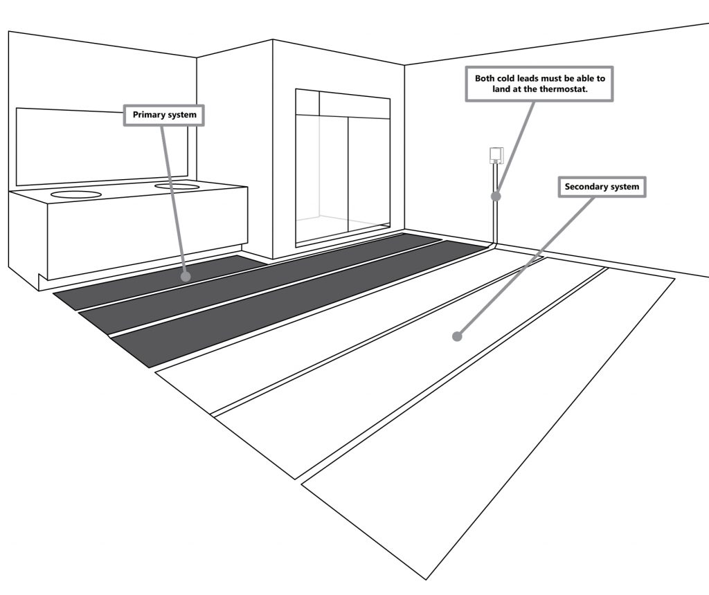
8.8.1 Option 1: Multiple Systems On One Thermostat (Single Circuit)
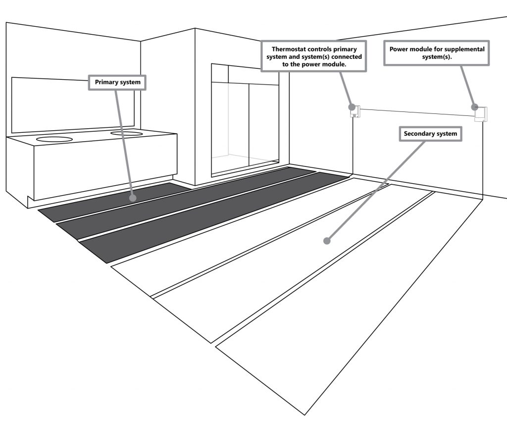
After you have measured your space(s), and determined which systems you will use, locating the thermostat is important. The systems cold lead’s must be able to be terminated at the thermostat in order to be controlled simultaneously. The diagram below gives an example of how two systems should be laid out.
If there are two separate spaces to be heated, the thermostat should be located on a shared wall where cold leads can be connected at the thermostat.
8.8.2 Option 2: Multiple Systems Using A Thermostat & Power Module (Double Circuit)
If the desired method is to use multiple Heatwave systems with a thermostat and a power module, determine which systems will be connected to which unit ensuring that neither system exceeds 15 amps. In this method, the cold leads must be able to reach the designated unit in order to work properly. The diagram below shows an example of how this can be accomplished. The power module is connected to the thermostat via a wired connection. Therefore, as long as the thermostat and power module can be connected via this wire, the location of the power module has no location restrictions outside of local codes. The power module uses a standard single-gang electrical box for wall installation.
Do NOT exceed 15 amps for either the thermostat or power module.
Failure to connect the power module to the thermostat will result inany systems connected to the power module to be non-functional.
8.9 Wiring Expansion Systems
8.9.1 Multiple Systems On One Thermostat (Single Circuit)
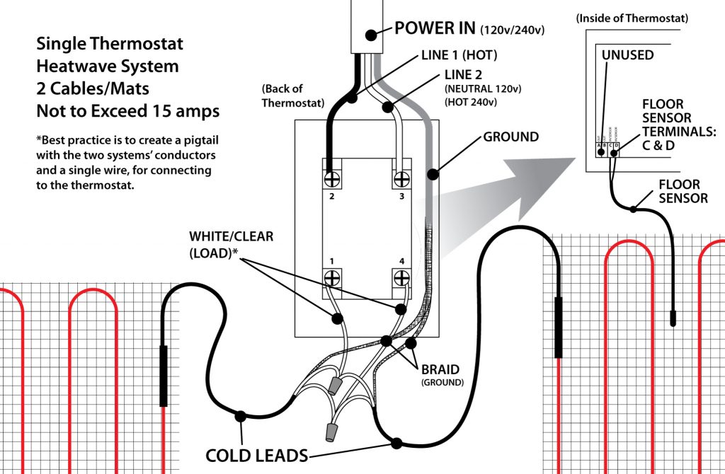
See the following diagram about how to wire multiple systems to a single thermostat or power module.
Do not run floor sensor wire in the same conduit as the cold lead(s), or connect them in anyway. There is a chance that electronic interference can cause issues with getting accurate readings from the floor sensor.
In the event that there is interest in adding more than one power module (more than two circuits), please contact Heatizon Systems (888.239.1232), for specific installation instructions for this application.
Best Practice is to create two pigtails, each with a conductor (from the cold lead) and a segment of wire, which is connected to the thermostat, reducing the amount of wires physically connected to the thermostat. Check local codes for further information.
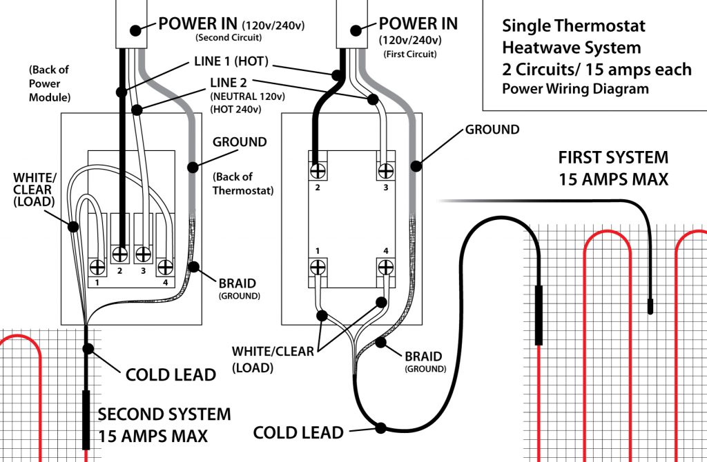
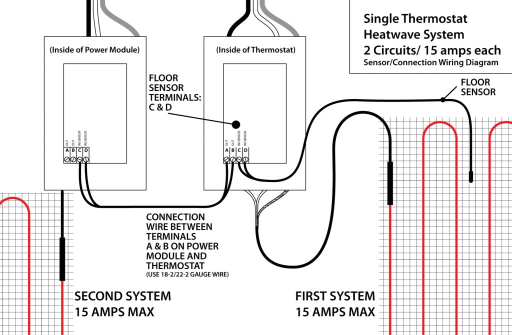
8.9.2 Multiple Systems Using A Thermostat & Power Module (Double Circuit)
See the following diagrams about how to wire multiple systems to a thermostat and a power module.
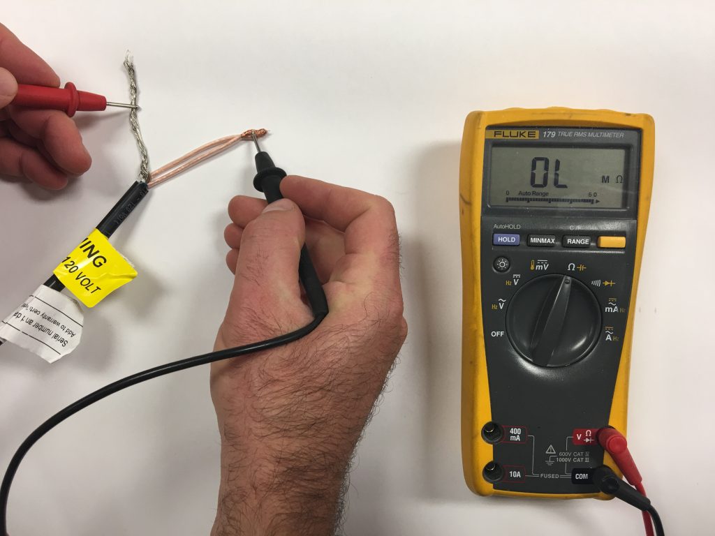
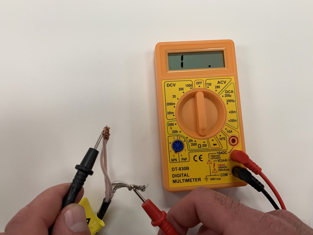
This test ensures that the insulating jackets of the heating cable are not damaged. A low value indicates the cable has been damaged and must be replaced.
Set the multimeter to 2000K ohm.
Connect* the ground wire to the black lead and both white conductors to the red lead of the multimeter.
Make sure the meter indicates, “Open,” “OL,” “1,” or infinity. If there is a different reading, contact Heatizon at 888-239-1232.
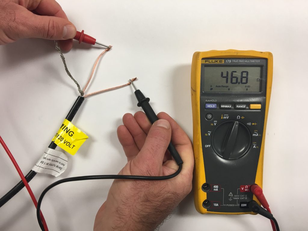
This test measures the resistance of the Heatwave® Mat or Cable, and is used to determine circuit integrity.
Set the multimeter to the 200 or 2000 ohm range.
Connect* the multimeter leads, one to each white conductor on the cold lead.
Compare this resistance reading to the resistance specified in the tables in Section 4.1 or 4.2. The value should be within ±10%. If there is a different reading than expected, contact Heatizon at 888-239-1232.
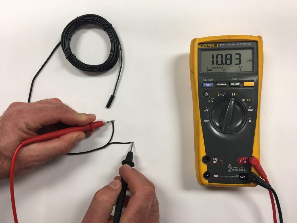
This test measures the resistance of the floor sensor and is used to verify the sensor integrity.
Set the multimeter to the 200K ohm range.
Connect* the multimeter leads to each sensor lead wire.
Make sure the meter reads between 9-25K ohms.
If there is a different reading, contact Heatizon at 888-239-1232.
* Be sure when connecting the multimeter to the leads, do not touch the connection with bare hands or that two connections do not touch.
7.4 USING A FLOOR ALARM/SCREAMER
If a floor alarm/screamer unit is being used that was part of the Heatwave® Premium Kits or purchased separately, follow the following instructions for use.
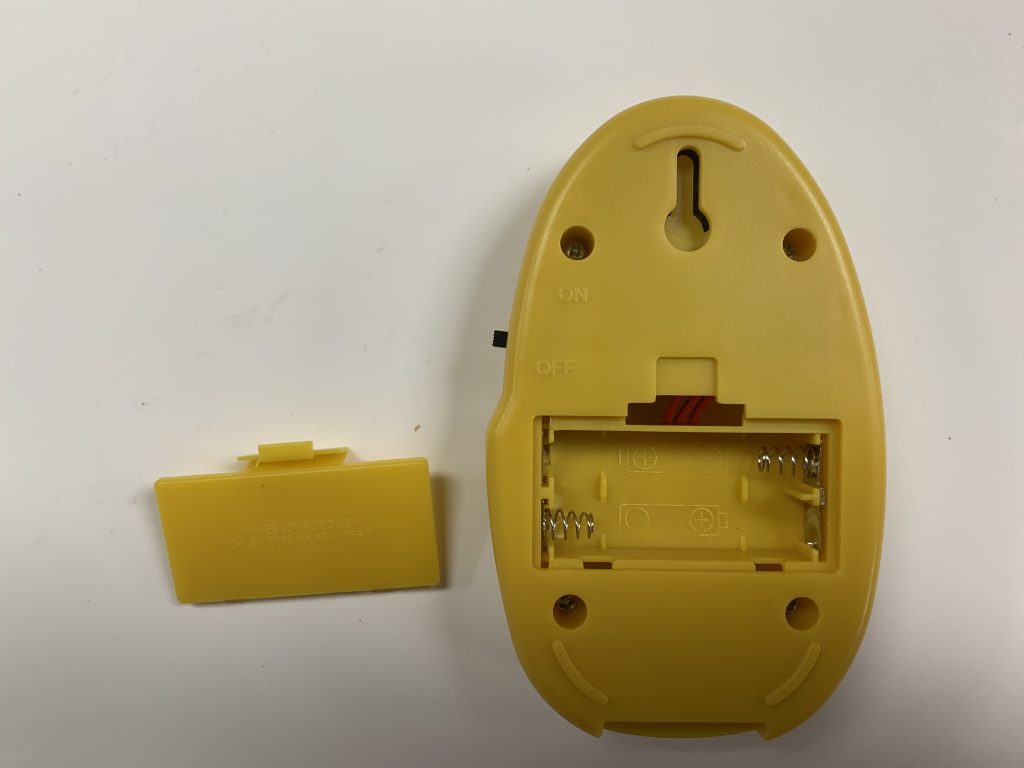
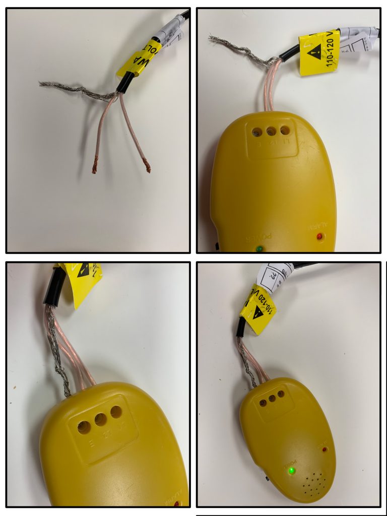
Install two AAA batteries (included with Premium Kits) by removing compartment on the backside of the device, close the compartment.
Switch the power on to the unit using the power switch, the device alarm should sound, also the power and alarm lights should illuminate. If the unit does not power on correctly, check to see if batteries are installed properly. Power the unit off.
Be sure the cold lead has been ran into the connection box/thermostat location, BEFORE beginning the layout of the Heatwave® cable or mat.
Connect the two copper wires with clear/white sheath to the terminals marked “L1” and “L2” on the floor alarm, using the screwdriver supplied, making sure the terminals are tightly screwed down.
Twist the silver ground wire tight and connect to the terminal marked “E/G,” again ensure the terminal is screwed down tight.
Power on the unit, the device should NOT make a sound and only the POWER light should illuminate, if the ALARM light is lit and the alarm sounds, turn it off and check the connections and power the unit back on.
Leave the floor alarm connected* and powered on whenever working on the Heatwave® system until it has been fully installed and flooring is complete, remove only when the system needs to be connected to the thermostat. *Only disconnect the floor alarm when the manual requires the Heatwave system be tested using a multimeter, then reconnect after testing is complete.
After you have finished using the Floor Alarm you may visit Heatizon.com/alarmrecycle to recycle the alarm responsibly and free of charge.
WARNING: IF THE FLOOR ALARM SOUNDS DURING THE INSTALLATION OF THE HEATWAVE® SYSTEM, STOP AND CHECK GROUND AND RESISTANCE (SECTION 7.1 AND 7.2), IF THE RESULTS DO NOT MATCH TO THE CHARTS, THE SYSTEM IS DAMAGED. CONTACT HEATIZON SYSTEMS 1-888-239-1232 FOR FURTHER INSTRUCTIONS ON HOW TO PROCEED WITH A REPAIR.
The Floor Alarms are specifically designed to monitor floor heating systems only. Any use outside of that for which they are specifically designed, is not recommended. Heatizon is committed to responsibly recycling/disposing of these units free of charge. Visit Heatizon.com/alarmrecycle for more information.
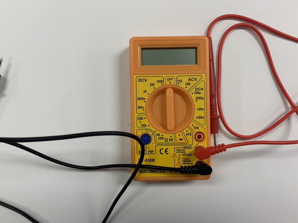
7.5 USING THE HEATIZON MULTIMETER
This multimeter is supplied with the Heatwave® Premium Kits or the Premium Add-on kit. This usage applies to testing the Heatwave® system only. For other uses/operations consult the devices manual*.
SETUP THE MULTIMETER:
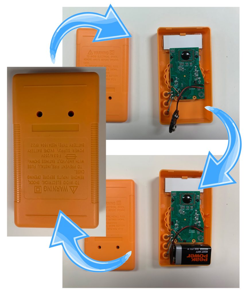
Install the battery (supplied) by removing the two screws on the back of the meter, then plugging the battery into the terminal inside. Replace the back of the meter and screw it tight.
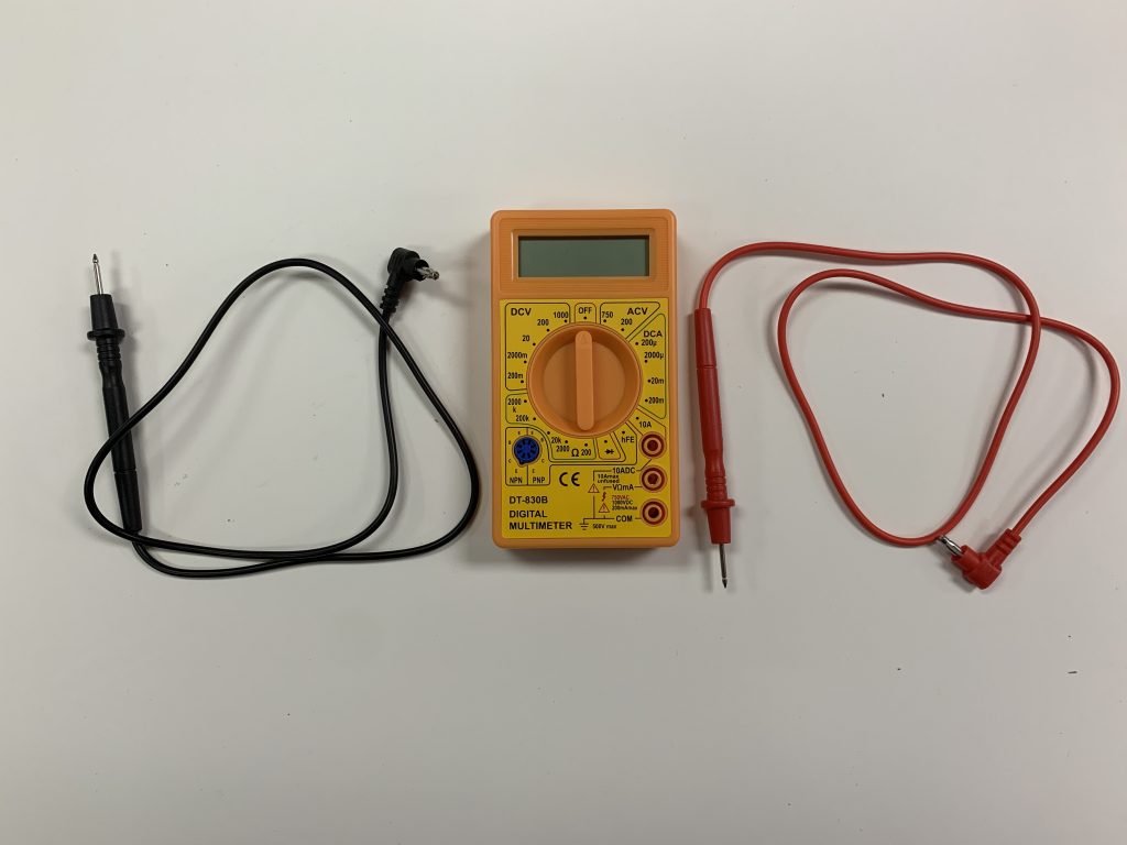
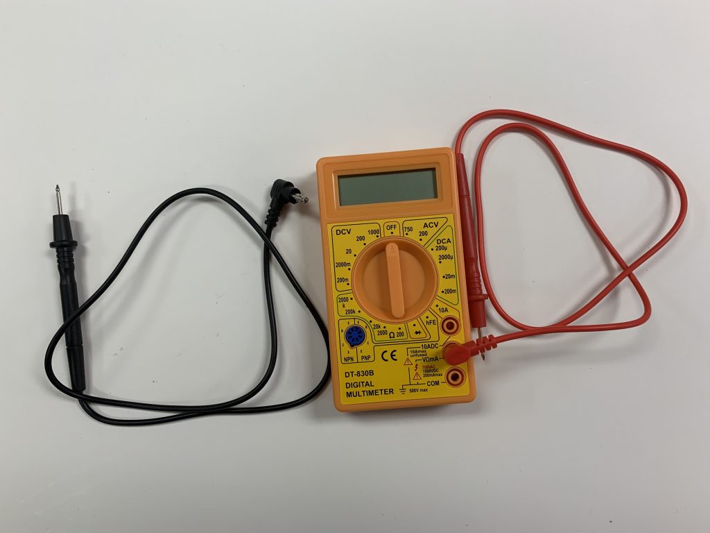
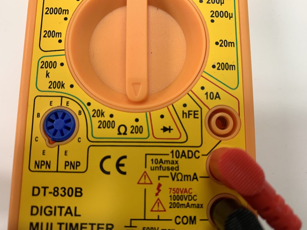
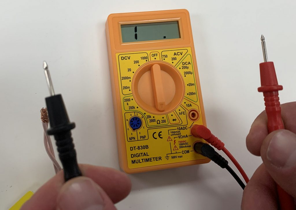
Install the red lead on the middle port on the front of the meter.
Install the black lead in the lower port on the front of the meter.
INSTALL RED PROBE
INSTALL BLACK PROBE
USING THE MULTIMETER:
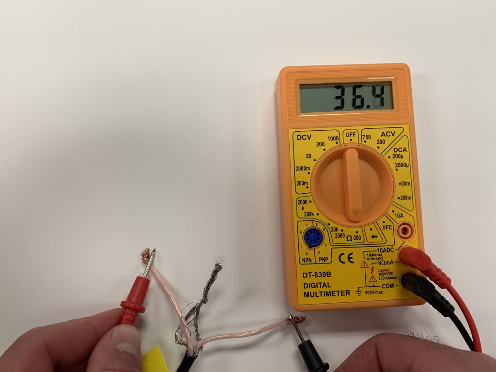
For the INSULATION RESISTANCE TEST (7.1) rotate the dial should be set to 200 in the Ohms section (Denoted by the Ω symbol) (Image 7.5A). Ensure that the display reads “1,” to indicate an open circuit (Image 7.5B) then proceed with the instructions outlined in step 7.1.
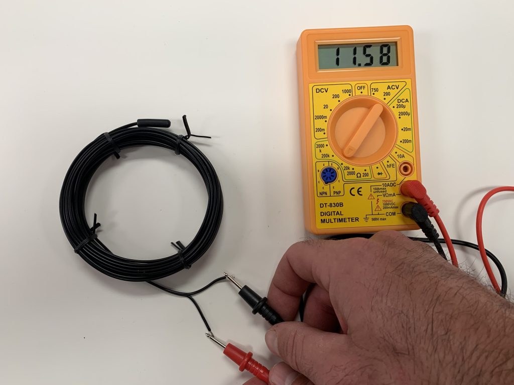
For the HEATING CABLE RESISTANCE TEST (7.2) keep the dial at the 200 ohms setting then proceed with the instructions outlined in step 7.2.
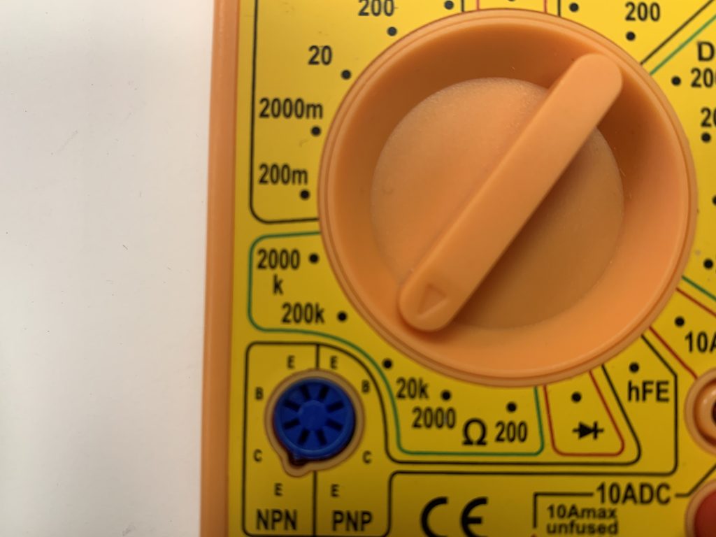
For the SENSOR RESISTANCE TEST (7.3), rotate the dial to the 20k ohm setting (image 7.5C) then proceed with the instructions outlined in step 7.3.
*Heatizon offers no warranty or support for the multimeter outside of this tutorial.
ENSURE THAT THE SENSOR CONDUIT HAS BEEN PROPERLY INSTALLED BEFORE PROCEEDING
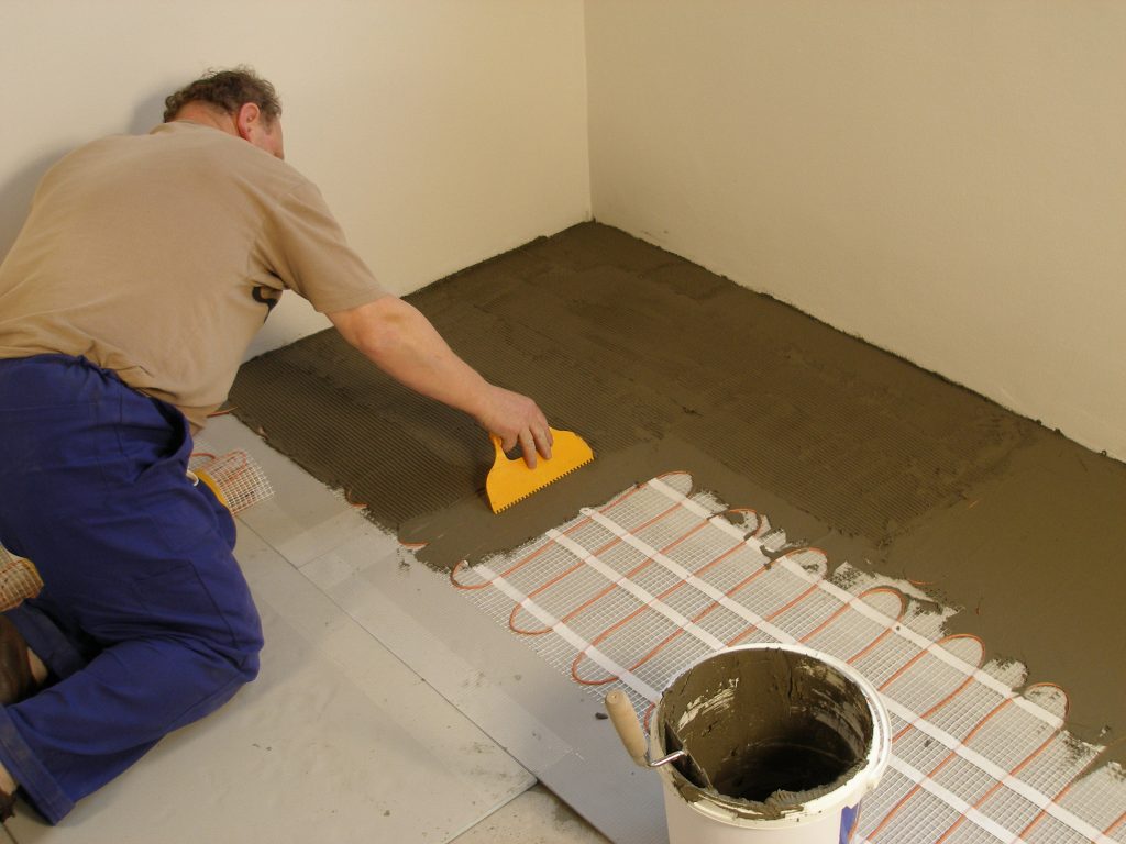
In the case of tiles, proceed with the installation of the tiles by covering the heating cables with a layer of thin-set cement as directed by the tile manufacturer. Ensure that the thin-set mortar covers the entire height of the heating cable as the tiles are installed. In the case of a wood, engineered or laminate floor covering, it is recommended that the flooring manufacturer be contacted. For wooden floors, a minimum of 3/16 in. of self leveling cement over the heating cable is recommended. Ensure that all moisture in the self-leveling cement has been fully eliminated in accordance with the drying times recommended by the manufacturer (consult the manufacturer for exact drying time) prior to energizing the Heatwave® product. Do not use Heatwave® to dry self leveling or other cementitious material.
The system must not be turned on until the cementitious material has fully dried. A minimum of two weeks is recommended.
6.1 MEASURE THE RESISTANCE (TEST #3)
Use a digital Ohm meter to measure the resistance of the Heatwave® Mat/Cable and compare it to the total Ohms in the tables in Section 4.1 for Mats or in Section 4.2 for Cables. Record the measured resistance on the Registration Form. Documenting the resistance at each stage of installation is required for warranty purposes. Also, measure the resistance between each conductor and the shielding/ground wire. Both should read infinity. Please refer to Section 7 (Commissioning) for instructions on how to measure the resistance.
6.2 INSTALL FLOOR COVERING
To install tile, apply a layer of thin-set mortar using the ridged side of the trowel (use trowel provided in Heatwave Premium Kit). Tile and grout the floor using best industry practices and in accordance with instructions provided by the tile manufacturer.
6.3 CONNECT POWER SUPPLY AND THERMOSTAT
The connection of the power supply and the thermostat must be done by a qualified person in accordance with the National Electrical Code (NEC) and the Canadian Electrical Code (CEC). Connect the floor sensor to the thermostat, take the final resistance reading and record it on the Registration Form.
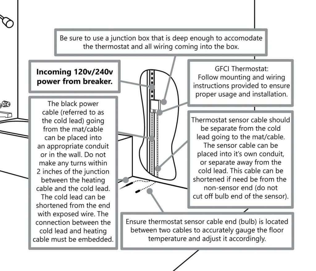
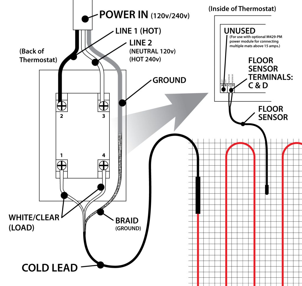
Electrical Connection Details
A deep, 2 1/8” X 4” single-gang junction box (or a “roomier” 4” X 4” double-gang box with a mud plate) should be provided by the electrician for the thermostat connections. See Rough-In Electrical Preparation Diagram below.
Mark the appropriate circuit breaker reference label indicating which branch circuit supplies the power to each electric heating cable.
All Electrical Connections for the Heatwave® Floor Warming System and Controls should be performed by a Professional Electrician in accordance with all Local and National Electrical Codes.
Thermostat Electrical Connection Details
This diagram is a quick reference for the connections for power and mat/cable to the M429 thermostat and the M429-PM (optional). Consult the diagrams included with the thermostat for further information. (Please see Section 8 for wiring multiple systems to a thermostat.)
The M429-PM is and optional device available from Heatizon for instances when multiple cables or mats need to be controlled by one thermostat, but exceed the amp rating of the single thermostat. For information about this advanced install method, read section 8. HEATWAVE EXPANSION.
Instructions for programming, wiring and troubleshooting of the M429 thermostat are included in the box and available on the Heatizon website.
The sensor cable and cold lead coming into the box for the thermostat can be shortened if needed.
Ensure that the sensor cable is separate from all power cables and enters into a different box port.
6.4 MEASURE THE RESISTANCE (TEST #4)
Use a digital Ohm meter to measure the resistance of the Heatwave® Mat/Cable and compare it to the total Ohms in the tables in Section 4.1 for Mats or in Section 4.2 for Cables. Record the measured resistance on the Registration Form. Documenting the resistance at each stage of installation is required for warranty purposes. Also, measure the resistance between each conductor and the shielding/ground wire. Both should read infinity. Please refer to Section 7 (Commissioning) for instructions on how to measure the resistance.
6.5 RECORD INFORMATION AND AFFIX LABELS
It is important for the home builder/owner to retain a copy and mail in the warranty certificate immediately after installing the system (Heatwave® Mat or Cable and Thermostat). Failure to do so could void the manufacturer’s warranty. The warranty is subject to the guarantee conditions listed on the warranty certificate. Keep a copy of the Registration Form for future reference. Place the included label “Electric Shock or Fire Hazard” on the inside of the electrical power distribution panel.
6.6 ENJOY THE COMFORT OF HEATWAVE
The Heatwave® Heating System is now ready to use. Increase the floor temperature gradually and adjust it until it reaches a comfortable level depending on the type of room and personal preferences.
Due to the varying thermal properties of rooms where the Heatwave® System may be installed, the size of the system installed, and the specific installation parameters, a firm time frame of how long it takes to heat to the desired temperature is hard to estimate without specific heat loss calculations.
Important: For the Limited Lifetime Warranty to apply, these tests MUST be performed, record the results on the Registration Form, and retain a copy of the record. These tests MUST be performed: Insulation Resistance Test, the Heating Cable Resistance Test, and the Sensor Resistance Test four times (please refer to Installation Instructions) during the installation process.
Visit section 7.5 for specific instructions about using the Heatizon Multimeter supplied in the Premium Kit/Premium Add-on Kit.
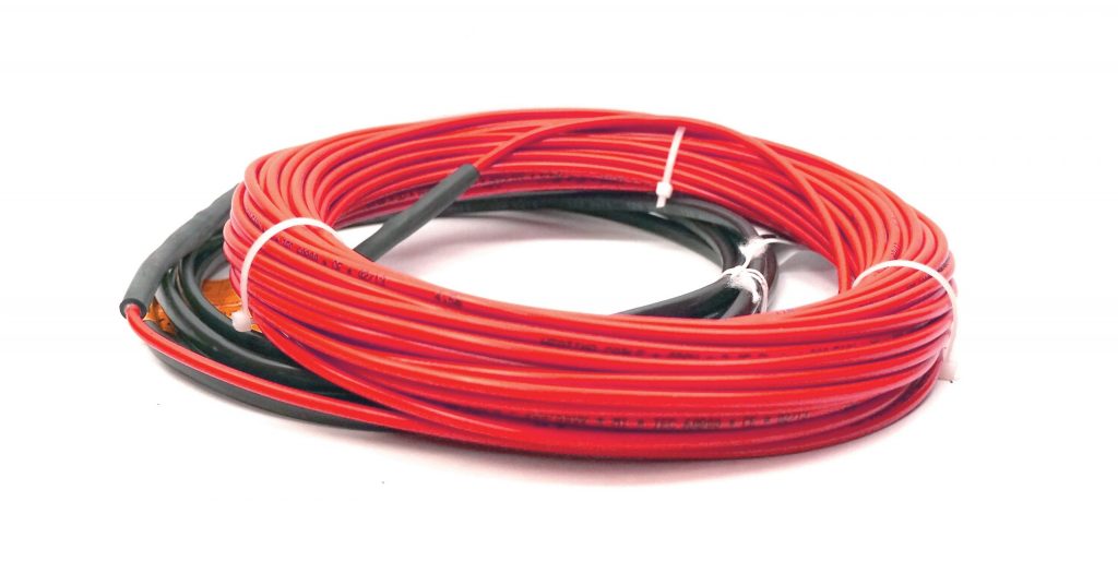
Verify the correct Heatwave® Cable has been purchased to heat the area selected and that the correct spacing has been determined for the area being heated, the Watts to be delivered, and the size of system purchased. DO NOT CUT THE RED HEATING CABLE to fit an area. See the Tables in Section 4.2.
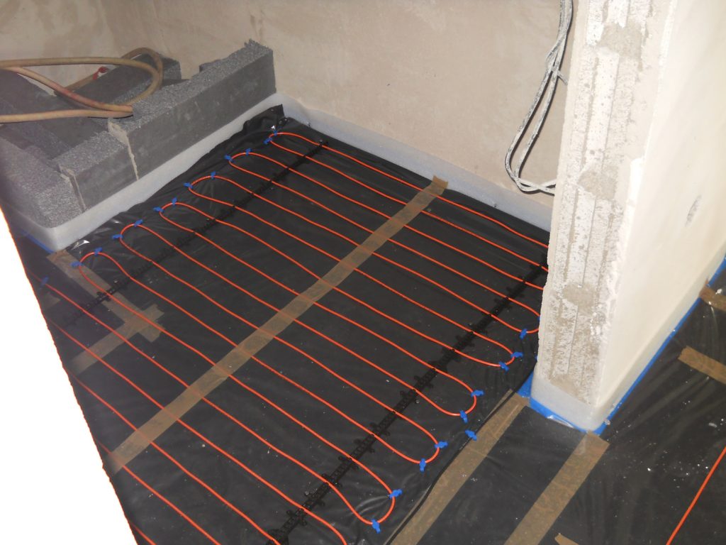
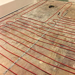
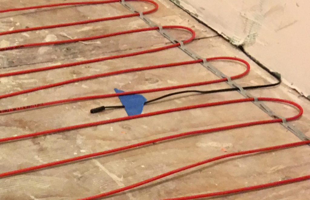
5.3.1 Plan room layout using tape measure, marking pencil, and chalk line. Lay out perimeter of area to be heated first, keeping a minimum of 1.5 inches from walls and or cabinets and the first run of element. Once the layout is complete, roll out the Heatwave® Heating Cable, making sure that both ends of the heating element (where the Heatwave® Heating Cable is pre-connected to the Cold Lead segment) are within 15 vertical and horizontal feet of the power switching thermostat location to accommodate Cold Lead length.
5.3.2 Start by placing the mat such that the connection point and the temperature sensor are in their intended final positions and bring the cold lead to the thermostat or connection box. If a floor alarm or “screamer box” is being used, attach it now (see section 7.4, FLOOR ALARM USAGE). Ensure the connection between the heating cable and cold lead will be properly embedded in thinset and/or mortar. Continue by laying out Heatwave® Heating Cable on the predetermined layout, and fasten with strapping or plastic clips as described below for the floor surface.
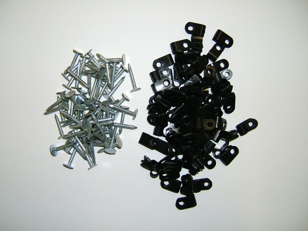
5.3.3 When anchoring the Heatwave® Heating Cable to wood subfloors use either the Plastic Clips (Heatizon Part PLASCLIPKIT) or Heatwave® Cable Strap (Heatizon Part HWCSTRAP33).
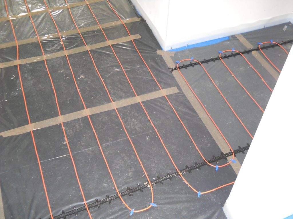
Plastic Clips: Each 90 degree bend and each 180 degree turn requires two Heatizon Plastic Clips. Heatizon Plastic Clips should be spaced approximately every 24 inches along the length of the Heating cable. Heatizon Plastic Clips can be inserted around Heatwave® Heating Cable, and secured to sub floor by hammering nail or driving a screw through anchor ends until both plastic tails are flat against sub floor surface. Repeat with each Heatizon Plastic Clip until all clips are secure.
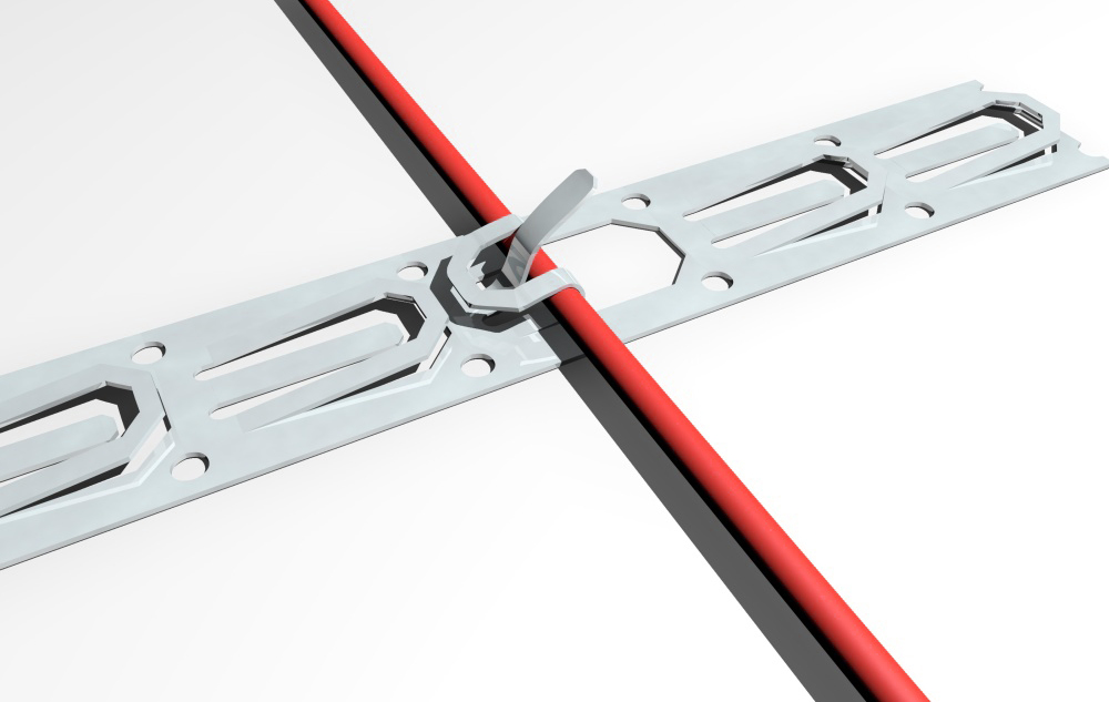
Cable Strap: Heatwave® Cable Strap is used to hold Heatwave® Cables in place on the sub floor surface at the spacing required. Variable spacing options can be maintained using this thin metal strapping. Cut the strap to length using ordinary snips. Anchor the strap with screws on plywood or backer board or with adhesive, hot glue or 2-sided tape on concrete. The strap should be installed on opposite ends of the room and every five feet in between. If additional securing of the cable is required, hot glue or tape can be used to hold in place during the thin set or self-leveling pour. Check continuity between the Heatwave® Heating Cable and the strap as the cable is installed.
5.3.4 If Heatwave® Heating Cable is being installed directly on existing concrete, a Heatwave® Anchoring Plug Kit (HWANCHPLUGKIT) may be purchased. Use a 1/4” cement drill bit to drill holes 1¼” deep in every location where a nail or screw will be located. Install one Anchoring Plug into each pre-drilled hole by tapping plugs until they are flush with the surface of the concrete. Anchoring Plugs should fit tightly in pre-drilled holes. If using Heatizon Plastic Clips, put a clip around Heatwave® Heating Cable and secure by hammering nail through anchor ends directly into the wood plug, until both plastic tails of the clip are flat against the concrete and plug. Repeat with each Heatizon Plastic Clip until all clips are secure.
5.3.5 Continue laying out and anchoring Heatwave® Heating Cable until complete. Make certain the end of the Cold Leads attached to the Heatwave® Heating Cable return to the thermostat location. When all of the Heatwave® Heating Cable has been installed and secured, run the second Cold Lead (if there are two) parallel to the first Cold Lead back to the thermostat, and secure both Cold Leads to the stud nearest the chosen location for the thermostat. Ensure the connection between the heating cable and cold lead will be properly embedded in thinset and/or mortar. This can be accomplished by routing out a small amount of the floor (create a small channel) to lower the profile of the connection.
5.3.6 MEASURE THE RESISTANCE (TEST #2)
Use a digital Ohm meter to measure the resistance of the Heatwave® Mat/Cable and compare it to the total Ohms in the tables in Section 4.1 for Mats or in Section 4.2 for Cables. Record the measured resistance on the Registration Form. Documenting the resistance at each stage of installation is required for warranty purposes. Also, measure the resistance between each conductor and the shielding/ground wire. Both should read infinity. Please refer to Section 7 (Commissioning) for instructions on how to measure the resistance.
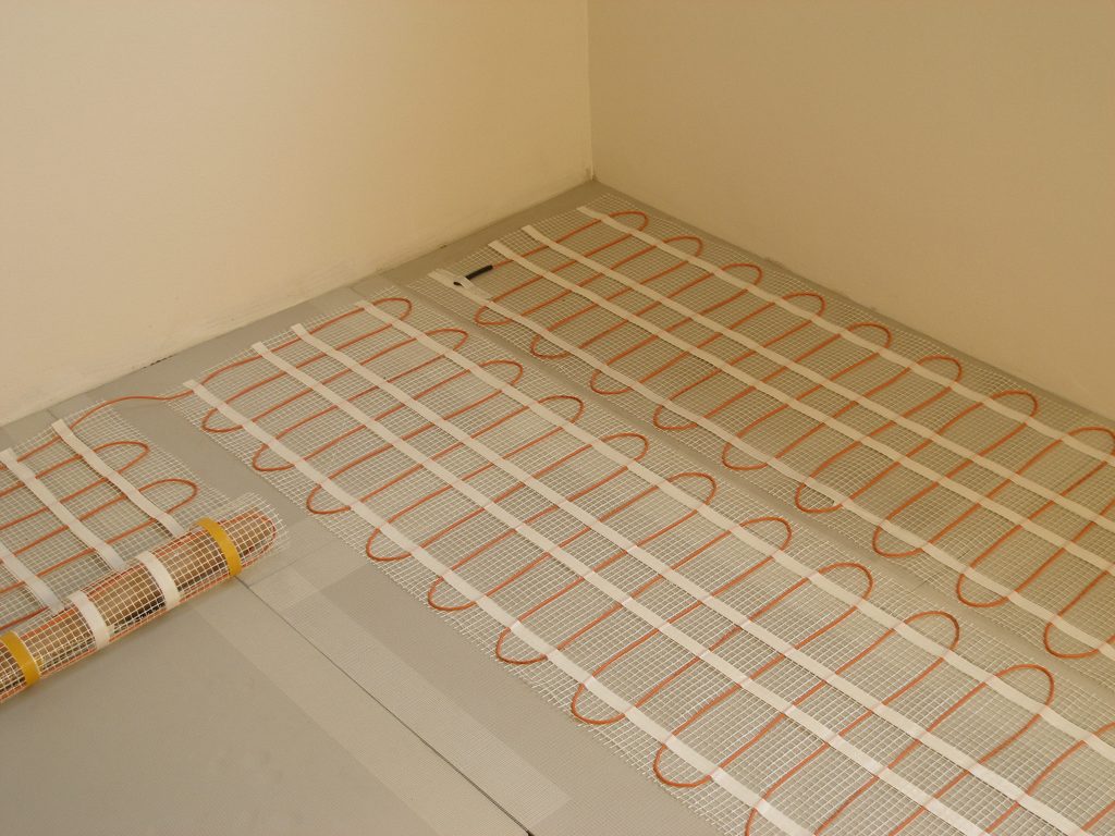
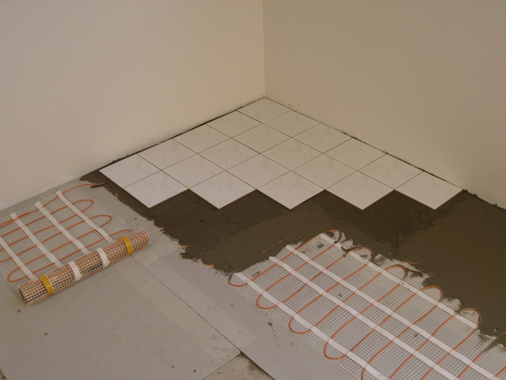
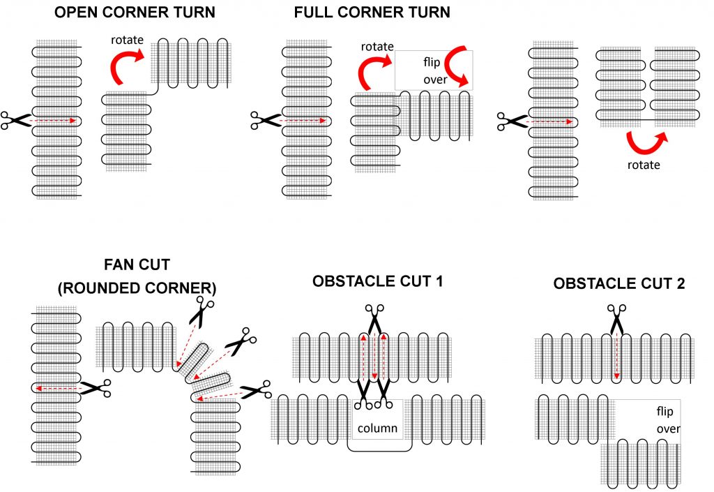
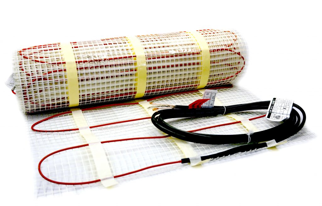
5.2.1 Start by placing the mat such that the connection point and the temperature sensor are in their intended final positions and bring the cold lead to the thermostat or connection box. If a floor alarm or “screamer box” is being used, attach it now (see section 7.4, FLOOR ALARM USAGE). Ensure the connection between the heating cable and cold lead will be properly embedded in thinset and/or mortar. Begin unrolling the Heatwave® Mat evenly across the floor outside the areas that were marked previously. When the next wall is reached, cut the mesh (being careful not to cut the red heating cable), turn the mat, and begin rolling in the desired direction. See Heatwave® Mat Layout Configurations on Page 17.
5.2.2 Ensure that the Heatwave® is in full contact with the subfloor at all times. Avoid walking on the heating mat. If this is not possible, use shoes with very soft rubber soles. When approaching obstacles (toilets, cabinets, etc.), carefully remove some of the red heating cable from the mat and lead the cable around the obstacle. In some cases pieces of the mesh will be cut away entirely. DO NOT CUT THE RED HEATING CABLE.
5.2.3 Use Heatizon Plastic Cable Clips, hot glue*, or a thin strip of tape to secure the loose cable to the floor. *Do not place hot glue gun tip directly on heating cable.
5.2.4 MEASURE THE RESISTANCE (TEST #2)
Use a digital Ohm meter to measure the resistance of the Heatwave® Mat/Cable and compare it to the total Ohms in the tables in Section 4.1 for Mats or in Section 4.2 for Cables. Record the measured resistance on the Registration Form. Documenting the resistance at each stage of installation is required for warranty purposes. Also, measure the resistance between each conductor and the shielding/ground wire. Both should read infinity. Please refer to Section 7 (Commissioning) for instructions on how to measure the resistance.
Heatwave® Mat Layout Configurations
The Heatwave Mat can be placed with either side facing up. Only the bottom side of the mat has adhesive.
Follow these steps to ensure a successful Heatwave® installation.
5.1.1 PLAN THE LAYOUT
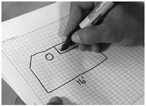
Make a sketch layout or a floor plan of the room; include all permanent furnishings such as toilets, bathtubs, appliances, cabinetry, etc. Indicate all dimensions required to determine the available floor area and the position of the thermostat.
Heatizon recommends that the installation be documented with photos and drawings to note the location of connections and the sensor, as well as the cable layout.
Important: Mark the position of the connection point between the power lead and the red Heatwave® heating cable. This connection must be embedded in cementitious material. When using a floor temperature sensing thermostat, mark the sensor position in the middle of two heating cables, about 10 in. (25 cm) away from the wall (within the heated area), as close as possible to the thermostat.
5.1.2 TRANSFER LAYOUT TO FLOOR
Draw an outline of the layout on the room floor including a foot print of all furnishings that are not yet installed. Unroll the first few feet of the Heatwave® Mat or Cable. The starting point of the cable must be placed within 15ft. of the thermostat.
5.1.3 INSTALL SENSOR
Heatwave Floor Sensor
If using a floor temperature sensing thermostat, install the sensor now, either in conduit tube, or directly to the subfloor. The sensor and/or tube needs to be installed between the thermostat wall box and the sensor position. The conduit tube must be partially countersunk into the subfloor. Cut a channel in the floor to a location below the thermostat for the sensor conduit. The conduit has to go from the wall below the thermostat and minimum of 10” away from the wall towards the middle of the floor for placement between two runs of cable.
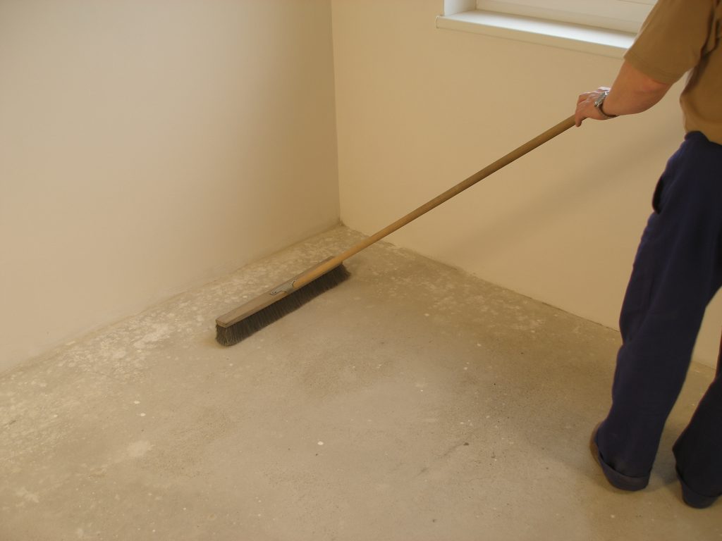
5.1.4 PREPARE SUBFLOOR SURFACE
Clean and vacuum the floor thoroughly and remove dust and debris from the floor that may damage the heating cable. Ensure that the subfloor is secure and stable. Carefully fill in all cracks to prevent any potential damage to the new tiles resulting from shifts in the subfloor.
5.1.5 MEASURE THE RESISTANCE (TEST #1)
Use a digital Ohm meter to measure the resistance of the Heatwave® Mat/Cable and compare it to the total Ohms in the tables in Section 4.1 for Mats or in Section 4.2 for Cables. Record the measured resistance on the Registration Form. Documenting the resistance at each stage of installation is required for warranty purposes. Also, measure the resistance between each conductor and the shielding/ground wire. Both should read infinity or open. Please refer to Section 7 (Commissioning) for instructions on how to measure the resistance.
NEVER CUT OR SHORTEN THE RED HEATING CABLE! DO NOT STAPLE THE RED HEATWAVE® HEATING CABLE. STAPLE ONLY THE WEBBING ON HEATWAVE® MATS WHERE NO CABLE IS LOCATED! NEVER PLACE RED CABLE WITHIN 6” OF A WAX TOILET RING.
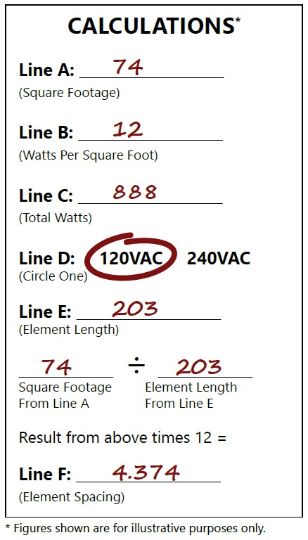
The Heatwave® Heating Cable comes in pre-established lengths that have been designed to deliver a specified watt density (see page 14 for models). To ensure that the Heatwave® Heating Element length purchased is the correct size for the project, complete this simple worksheet prior to beginning the installation process.
Calculate Square Footage to be Heated. Determine the square footage of the area to be warmed. Note: this is not necessarily the same as the room dimensions. Enter the total square footage on line A.
Determine Watts Per Square Foot. Determine the Watts per square foot for the application. Heatizon Systems suggests the following Watts per square foot:
Floor Warming—8 to 15 Watts per square foot
Space Heating—Watts per square foot and spacing between element runs should be determined by a heat loss calculation. Contact Heatizon Systems for information on how to obtain a heat loss calculation. Enter the desired total Watts per square foot on Line B.
Calculate Total Watts. Calculate total Watts by multiplying Line A by Line B, and enter the result on Line C.
Determine Input Voltage. Determine if the Heatwave® Heating Cable will be powered by 120VAC or 240VAC, and check the correct input voltage on Line D.
Select the Correct Heatwave® Heating Cable Length. Use the table below to select the Heatwave® Heating Cable Model that is the correct input Voltage from line D, and will deliver the closest total watts calculated on Line C. Heatizon Systems recommends selecting the next larger Heatwave® Heating Cable Length if the total Watts calculated in Step 3 is between two models. Select the model number, and write the corresponding Element “Cable Length” on Line E.
Calculate Element Spacing. Calculate the amount of space between the runs of element for the application and the Heatwave® Heating Element.
Important: Tools and materials required The following items may be required to install and test the floor heating system:
Scissors
Tape measure
Wire strippers
Screwdriver
Tin snips
Utility knife
Plastic Cable Clips or Strapping
Hot glue gun
Multimeter
Before Laying the Heatwave® Mat or Cable Note: Measure the resistance between each conductor and the shielding/ground wire. Both should read infinity. Always complete a Heatizon Systems “Resistance in OHMS Form” (see form in the back of this manual) out of the box, immediately following the installation of the Heatwave® Heating Cable/Mat, immediately prior to covering the Heatwave® Heating Cable/Mat, and again just prior to energizing the Heatwave® Heating Cable/Mat.
Confirm that Heatwave® product is no larger than the heated area. Following the example from Figure 3, if the heated area is 74 ft2, select the 70 ft2 Heatwave® Heating Mat.
Heatwave® Mats, 12 Watts/Ft2, 120 VAC
Heatizon Part Number
Manufacturer Number
Total Watts
Total Ohms
Amp Load
Watts/ Foot
Coverage Area/Square Foot
Watts/ Square Foot
Mat Length
Mat Width
Cable spacing (O.C.)
14AWG Cold Lead Length
HW2012-100
HW2012-10
120
120.0
1.0
2.73
10
12.00
6.1′
20”
2.90″
15′
HW2012-150
HW2012-15
180
80.0
1.5
3.59
15
12.00
9.1′
20”
3.81″
15′
HW2012-200
HW2012-20
240
60.0
2.0
3.13
20
12.00
12.2′
20”
3.33″
15′
HW2012-250
HW2012-25
300
48.0
2.5
2.63
25
12.00
15.2′
20”
2.79″
15′
HW2012-300
HW2012-30
360
40.0
3.0
2.55
30
12.00
18.3′
20”
2.71″
15′
HW2012-350
HW2012-35
420
34.3
3.5
3.47
35
12.00
21.3′
20”
3.69″
15′
HW2012-400
HW2012-40
480
30.0
4.0
3.12
40
12.00
24.4′
20”
3.31″
15′
HW2012-500
HW2012-50
600
24.0
5.0
3.20
50
12.00
30.5′
20”
3.40″
15′
HW2012-600
HW2012-60
720
20.0
6.0
3.40
60
12.00
36.6′
20”
3.61″
15′
HW2012-700
HW2012-70
840
17.1
7.0
2.93
70
12.00
42.7′
20”
3.11″
15′
HW2012-800
HW2012-80
960
15.0
8.0
2.65
80
12.00
48.8′
20”
2.82″
15′
HW2012-900
HW2012-90
1080
13.3
9.0
3.36
90
12.00
54.9′
20”
3.56″
15′
HW2012-1000
HW2012-100
1200
12.0
10.0
4.15
100
12.00
61.0′
20”
4.44″
15′
Heatwave® Mats, 12 Watts/Ft2, 240 VAC
Heatizon Part Number
Manufacturer Number
Total Watts
Total Ohms
Amp Load
Watts/ Foot
Coverage Area/Square Foot
Watts/ Square Foot
Mat Length
Mat Width
Cable spacing (O.C.)
14AWG Cold Lead Length
HW2012-400B
HW2024-40
480
120.0
2.0
3.13
40
12.00
24.4′
20”
3.33″
15′
HW2012-500B
HW2024-50
600
96.0
2.5
2.63
50
12.00
30.5′
20”
2.79″
15′
HW2012-600B
HW2024-60
720
80.0
3.0
2.55
60
12.00
36.6′
20”
2.71″
15′
HW2012-700B
HW2024-70
840
68.6
3.5
2.39
70
12.00
42.7′
20”
2.54″
15′
HW2012-800B
HW2024-80
960
60.0
4.0
3.12
80
12.00
48.8′
20”
3.31″
15′
HW2012-900B
HW2024-90
1080
53.3
4.5
2.59
90
12.00
54.9′
20”
2.75″
15′
HW2012-1000B
HW2024-100
1200
48.0
5.0
3.20
100
12.00
61.0′
20”
3.40″
15′
HW2012-1100B
HW2024-110
1320
43.6
5.5
2.86
110
12.00
67.1′
20”
3.03″
15′
HW2012-1200B
HW2024-120
1440
40.0
6.0
3.40
120
12.00
73.2′
20”
3.61″
15′
HW2012-1450B
HW2024-145
1740
33.1
7.3
3.14
145
12.00
88.4′
20”
3.33″
15′
HW2012-1600B
HW2024-160
1920
30.0
8.0
2.65
160
12.00
97.6′
20”
2.82″
15′
Important: Tools and materials required The following items may be required to install and test the floor heating system:
Scissors
Tape measure
Wire strippers
Screwdriver
Tin snips
Utility knife
Plastic Cable Clips or Strapping
Hot glue gun
Multimeter
Before Laying the Heatwave® Mat or Cable Note: Measure the resistance between each conductor and the shielding/ground wire. Both should read infinity. Always complete a Heatizon Systems “Resistance in OHMS Form” (see form in the back of this manual) out of the box, immediately following the installation of the Heatwave® Heating Cable/Mat, immediately prior to covering the Heatwave® Heating Cable/Mat, and again just prior to energizing the Heatwave® Heating Cable/Mat.