Completing Installation
ENSURE THAT THE SENSOR CONDUIT HAS BEEN PROPERLY INSTALLED BEFORE PROCEEDING
In the case of tiles, proceed with the installation of the tiles by covering the heating cables with a layer of thin-set cement as directed by the tile manufacturer. Ensure that the thin-set mortar covers the entire height of the heating cable as the tiles are installed. In the case of a wood, engineered or laminate floor covering, it is recommended that the flooring manufacturer be contacted. For wooden floors, a minimum of 3/16 in. of self leveling cement over the heating cable is recommended. Ensure that all moisture in the self-leveling cement has been fully eliminated in accordance with the drying times recommended by the manufacturer (consult the manufacturer for exact drying time) prior to energizing the Heatwave® product. Do not use Heatwave® to dry self leveling or other cementitious material.

The system must not be turned on until the cementitious material has fully dried. A minimum of two weeks is recommended.
6.1 MEASURE THE RESISTANCE (TEST #3)
Use a digital Ohm meter to measure the resistance of the Heatwave® Mat/Cable and compare it to the total Ohms in the tables in Section 4.1 for Mats or in Section 4.2 for Cables. Record the measured resistance on the Registration Form. Documenting the resistance at each stage of installation is required for warranty purposes. Also, measure the resistance between each conductor and the shielding/ground wire. Both should read infinity. Please refer to Section 7 (Commissioning) for instructions on how to measure the resistance.
6.2 INSTALL FLOOR COVERING
To install tile, apply a layer of thin-set mortar using the ridged side of the trowel (use trowel provided in Heatwave Premium Kit). Tile and grout the floor using best industry practices and in accordance with instructions provided by the tile manufacturer.
6.3 CONNECT POWER SUPPLY AND THERMOSTAT
The connection of the power supply and the thermostat must be done by a qualified person in accordance with the National Electrical Code (NEC) and the Canadian Electrical Code (CEC). Connect the floor sensor to the thermostat, take the final resistance reading and record it on the Registration Form.
Electrical Connection Details
A deep, 2 1/8” X 4” single-gang junction box (or a “roomier” 4” X 4” double-gang box with a
mud plate) should be provided by the electrician for the thermostat connections. See Rough-In
Electrical Preparation Diagram below.
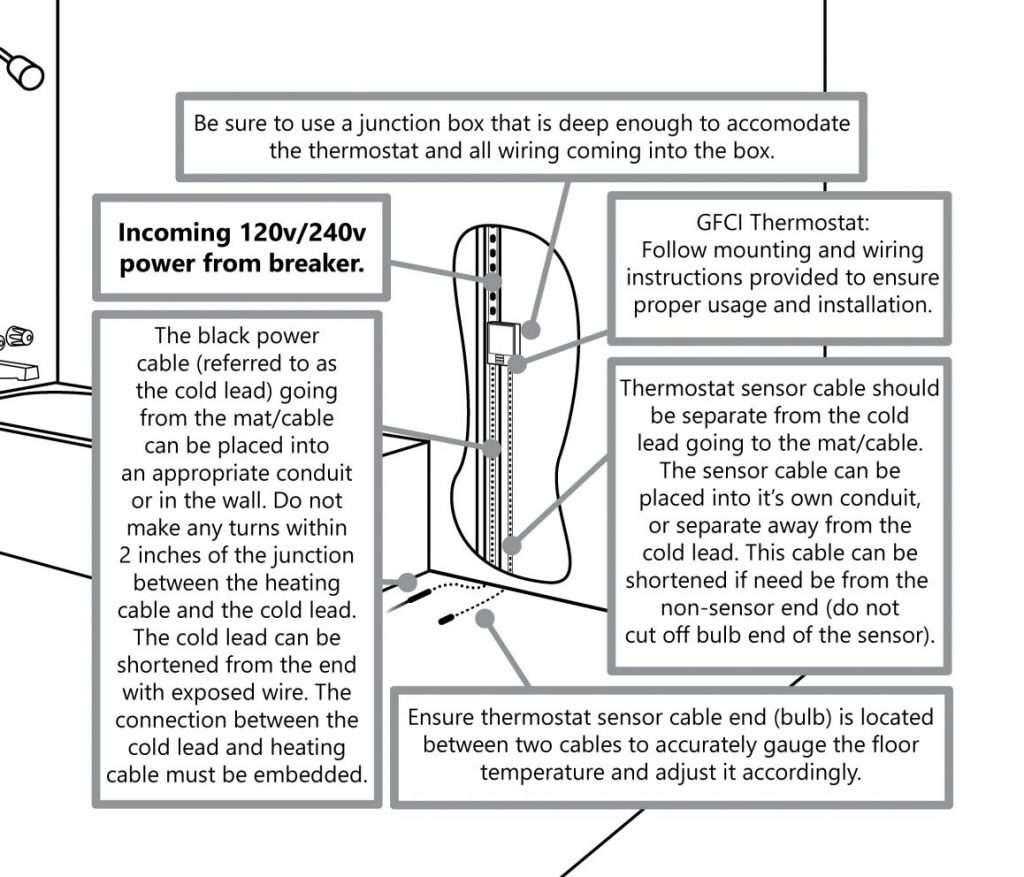
- Mark the appropriate circuit breaker reference label indicating which branch circuit supplies the power to each electric heating cable.
- All Electrical Connections for the Heatwave® Floor Warming System and Controls should be performed by a Professional Electrician in accordance with all Local and National Electrical Codes.
Thermostat Electrical Connection Details
This diagram is a quick reference for the connections for power and mat/cable to the M429 thermostat and the M429-PM (optional). Consult the diagrams included with the thermostat for further information. (Please see Section 8 for wiring multiple systems to a thermostat.)
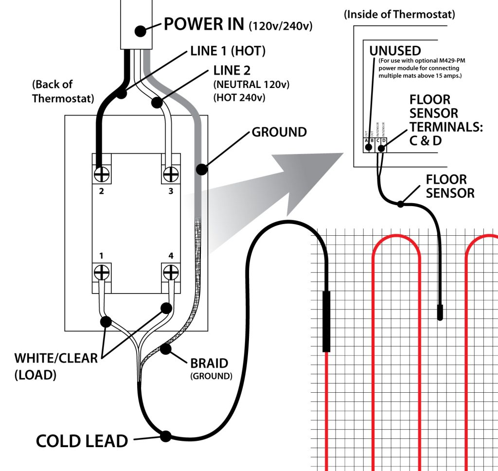
The M429-PM is and optional device available from Heatizon for instances when multiple cables or mats need to be controlled by one thermostat, but exceed the amp rating of the single thermostat. For information about this advanced install method, read section 8. HEATWAVE EXPANSION.
- Consult the quick start thermostat programming guide once the thermostat installation is completed.
- Instructions for programming, wiring and troubleshooting of the M429 thermostat are included in the box and available on the Heatizon website.
- The sensor cable and cold lead coming into the box for the thermostat can be shortened if needed.
- Ensure that the sensor cable is separate from all power cables and enters into a different box port.
6.4 MEASURE THE RESISTANCE (TEST #4)
Use a digital Ohm meter to measure the resistance of the Heatwave® Mat/Cable and compare it to the total Ohms in the tables in Section 4.1 for Mats or in Section 4.2 for Cables. Record the measured resistance on the Registration Form. Documenting the resistance at each stage of installation is required for warranty purposes. Also, measure the resistance between each conductor and the shielding/ground wire. Both should read infinity. Please refer to Section 7 (Commissioning) for instructions on how to measure the resistance.
6.5 RECORD INFORMATION AND AFFIX LABELS
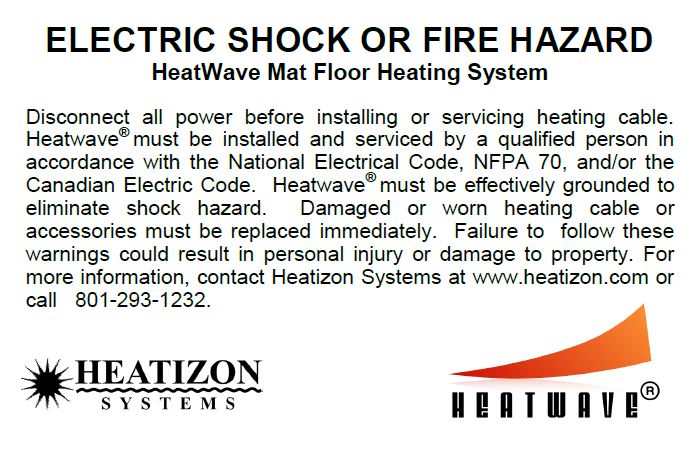
It is important for the home builder/owner to retain a copy and mail in the warranty certificate immediately after installing the system (Heatwave® Mat or Cable and Thermostat). Failure to do so could void the manufacturer’s warranty. The warranty is subject to the guarantee conditions listed on the warranty certificate. Keep a copy of the Registration Form for future reference. Place the included label “Electric Shock or Fire Hazard” on the inside of the electrical power distribution panel.
6.6 ENJOY THE COMFORT OF HEATWAVE
The Heatwave® Heating System is now ready to use. Increase the floor temperature gradually and adjust it until it reaches a comfortable level depending on the type of room and personal preferences.
Due to the varying thermal properties of rooms where the Heatwave® System may be installed, the size of the system installed, and the specific installation parameters, a firm time frame of how long it takes to heat to the desired temperature is hard to estimate without specific heat loss calculations.

Important: For the Limited Lifetime Warranty to apply, these tests MUST be performed, record the results on the Registration Form, and retain a copy of the record. These tests MUST be performed: Insulation Resistance Test, the Heating Cable Resistance Test, and the Sensor Resistance Test four times (please refer to Installation Instructions) during the installation process.
Visit section 7.5 for specific instructions about using the Heatizon Multimeter supplied in the Premium Kit/Premium Add-on Kit.