Category: 5. Installation

Heatwave Cable Installation

5.3 Heatwave® Cable Installation

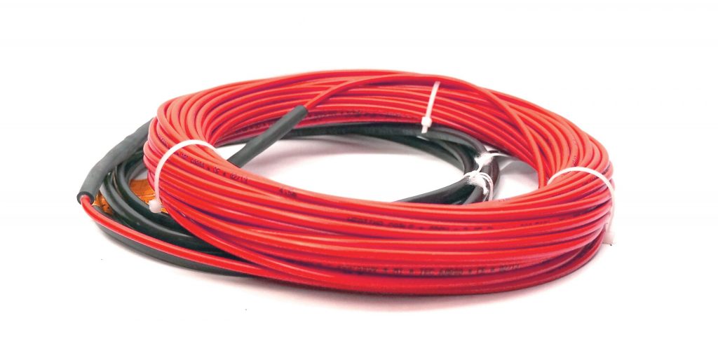
Verify the correct Heatwave® Cable has been purchased to heat the area selected and that the correct spacing has been determined for the area being heated, the Watts to be delivered, and the size of system purchased. DO NOT CUT THE RED HEATING CABLE to fit an area. See the Tables in Section 4.2.

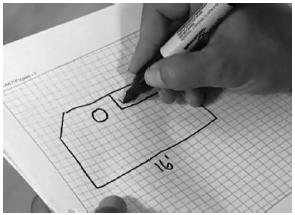
5.3.1 Plan room layout using tape measure, marking pencil, and chalk line. Lay out perimeter of area to be heated first, keeping a minimum of 1.5 inches from walls and or cabinets and the first run of element. Once the layout is complete, roll out the Heatwave® Heating Cable, making sure that both ends of the heating element (where the Heatwave® Heating Cable is pre-connected to the Cold Lead segment) are within 15 vertical and horizontal feet of the power switching thermostat location to accommodate Cold Lead length.

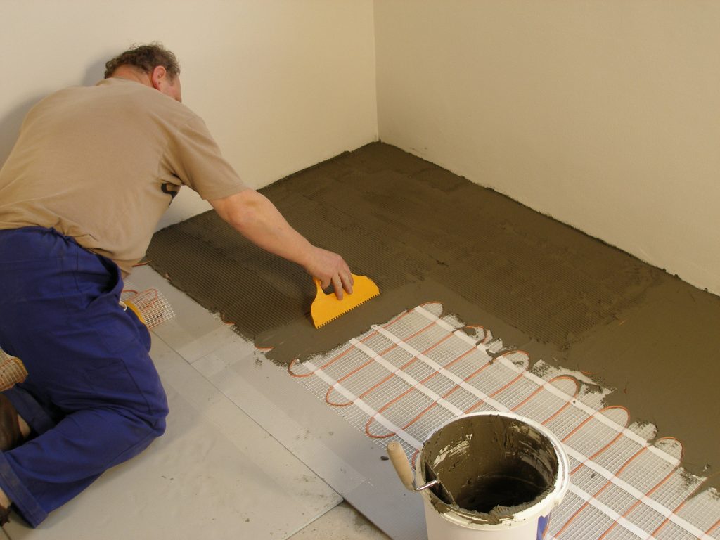
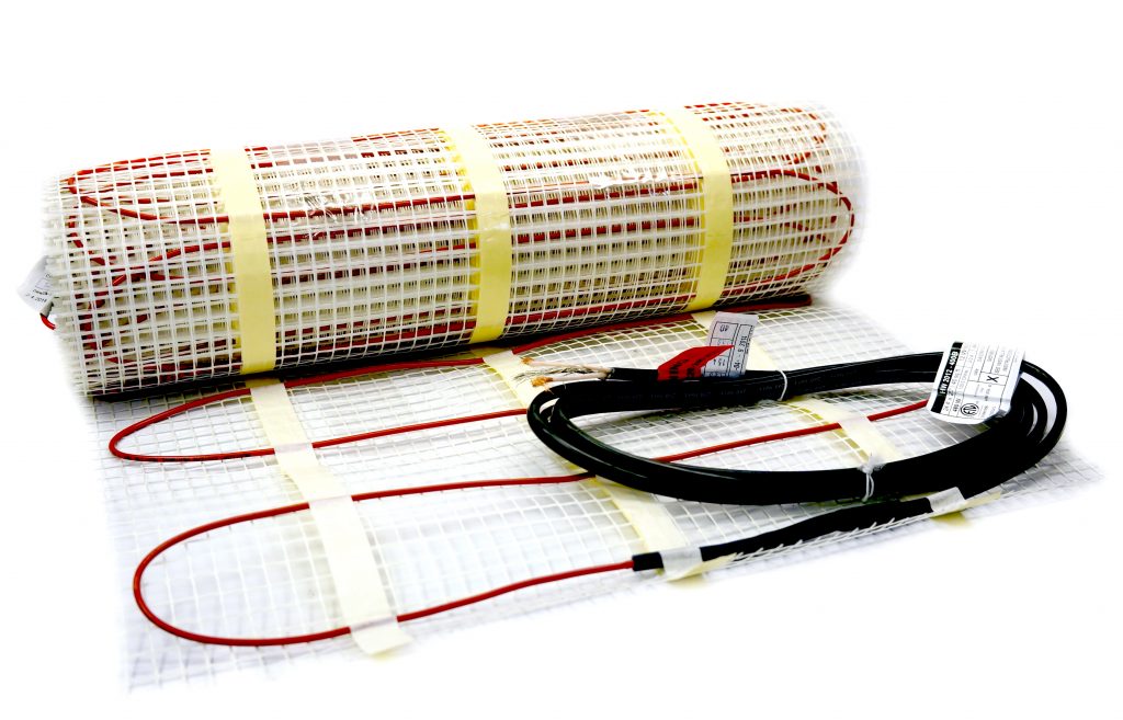
5.3.2 Start by placing the mat such that the connection point and the temperature sensor are in their intended final positions and bring the cold lead to the thermostat or connection box. If a floor alarm or “screamer box” is being used, attach it now (see section 7.4, FLOOR ALARM USAGE). Ensure the connection between the heating cable and cold lead will be properly embedded in thinset and/or mortar.
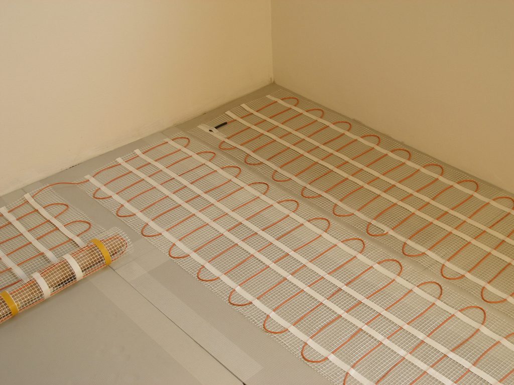
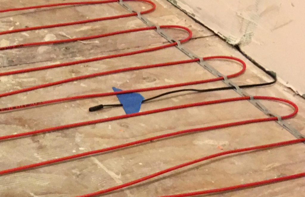
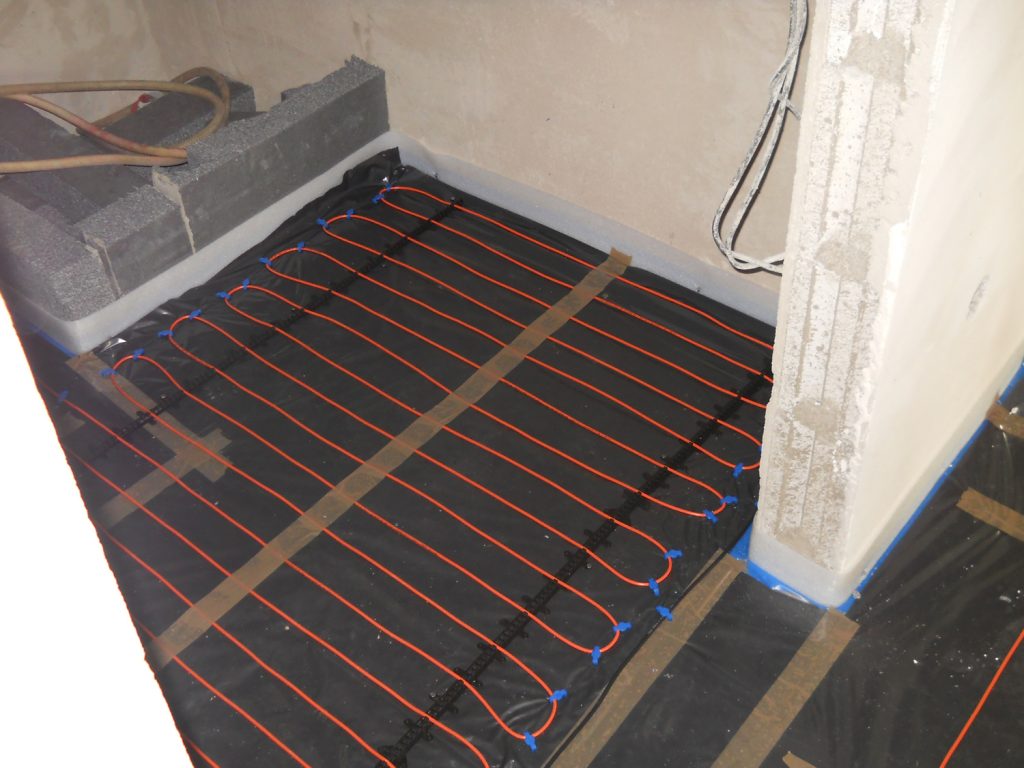
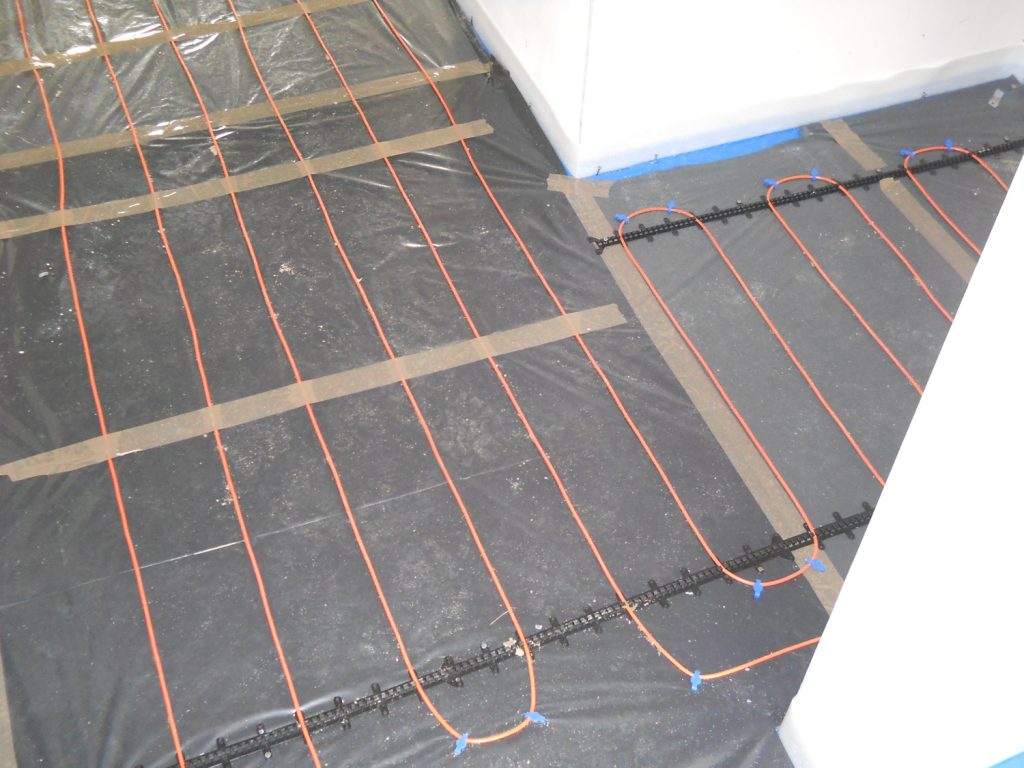
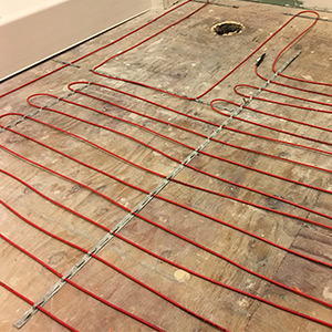
Continue by laying out Heatwave® Heating Cable on the predetermined layout, and fasten with strapping or plastic clips as described below for the floor surface.

5.3.3 When anchoring the Heatwave® Heating Cable to wood subfloors use either the Plastic Clips (Heatizon Part PLASCLIPKIT) or Heatwave® Cable Strap (Heatizon Part HWCSTRAP33).

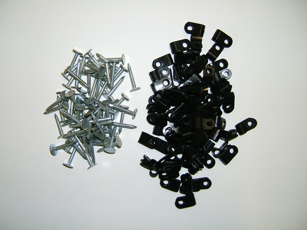
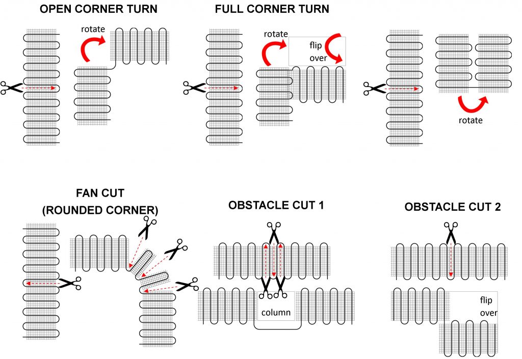
Plastic Clips: Each 90 degree bend and each 180 degree turn requires two Heatizon Plastic Clips. Heatizon Plastic Clips should be spaced approximately every 24 inches along the length of the Heating cable. Heatizon Plastic Clips can be inserted around Heatwave® Heating Cable, and secured to sub floor by hammering nail or driving a screw through anchor ends until both plastic tails are flat against sub floor surface. Repeat with each Heatizon Plastic Clip until all clips are secure.

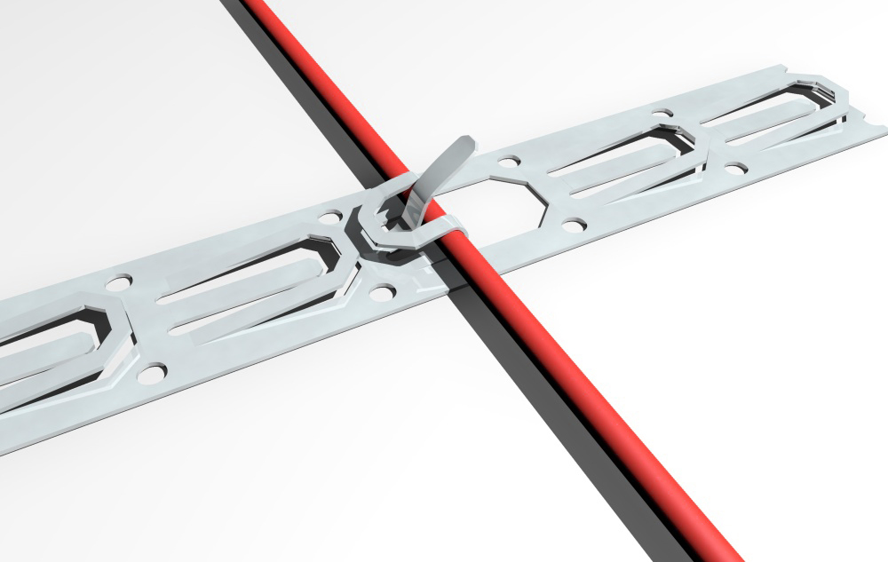
Cable Strap: Heatwave® Cable Strap is used to hold Heatwave® Cables in place on the sub floor surface at the spacing required. Variable spacing options can be maintained using this thin metal strapping. Cut the strap to length using ordinary snips. Anchor the strap with screws on plywood or backer board or with adhesive, hot glue or 2-sided tape on concrete. The strap should be installed on opposite ends of the room and every five feet in between. If additional securing of the cable is required, hot glue or tape can be used to hold in place during the thin set or self-leveling pour. Check continuity between the Heatwave® Heating Cable and the strap as the cable is installed.

5.3.4 If Heatwave® Heating Cable is being installed directly on existing concrete, a Heatwave® Anchoring Plug Kit (HWANCHPLUGKIT) may be purchased. Use a 1/4” cement drill bit to drill holes 1¼” deep in every location where a nail or screw will be located. Install one Anchoring Plug into each pre-drilled hole by tapping plugs until they are flush with the surface of the concrete. Anchoring Plugs should fit tightly in pre-drilled holes. If using Heatizon Plastic Clips, put a clip around Heatwave® Heating Cable and secure by hammering nail through anchor ends directly into the wood plug, until both plastic tails of the clip are flat against the concrete and plug. Repeat with each Heatizon Plastic Clip until all clips
are secure.

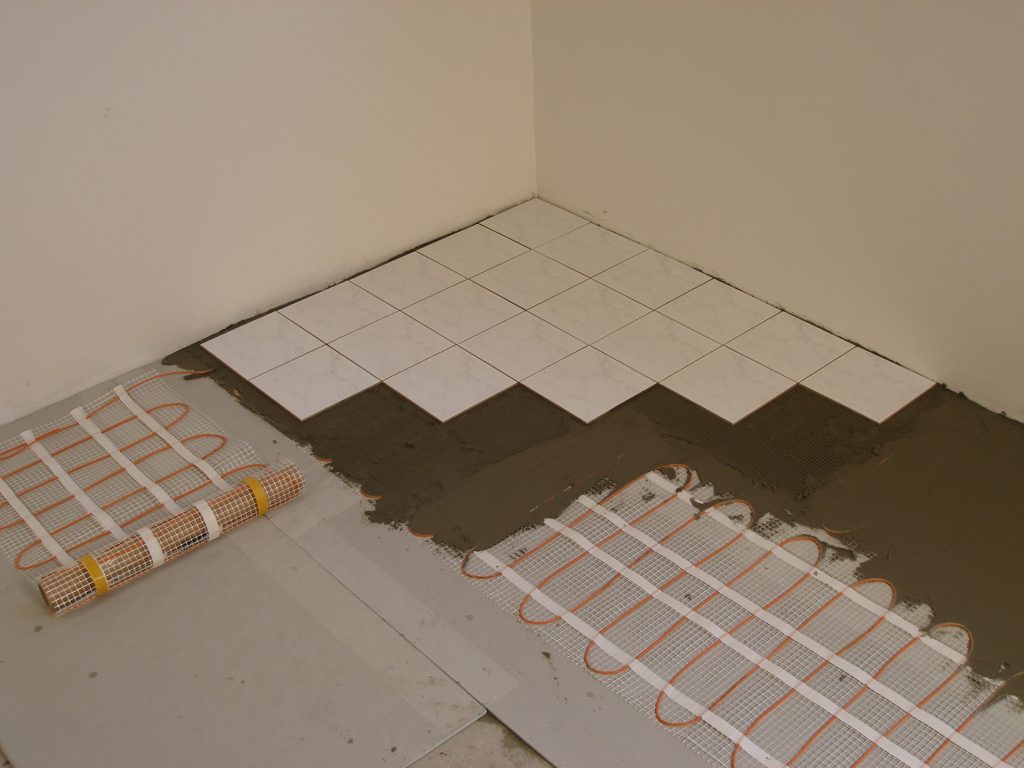
5.3.5 Continue laying out and anchoring Heatwave® Heating Cable until complete. Make certain the end of the Cold Leads attached to the Heatwave® Heating Cable return to the thermostat location. When all of the Heatwave® Heating Cable has been installed and secured, run the second Cold Lead (if there are two) parallel to the first Cold Lead back to the thermostat, and secure both Cold Leads to the stud nearest the chosen location for the thermostat. Ensure the connection between the heating cable and cold lead will be properly embedded in thinset and/or mortar. This can be accomplished by routing out a small amount of the floor (create a small channel) to lower the profile of the connection.

5.3.6 MEASURE THE RESISTANCE (TEST #2)

Use a digital Ohm meter to measure the resistance of the Heatwave® Mat/Cable and compare
it to the total Ohms in the tables in Section 4.1 for Mats or in Section 4.2 for Cables. Record
the measured resistance on the Registration Form. Documenting the resistance at each stage
of installation is required for warranty purposes. Also, measure the resistance between each
conductor and the shielding/ground wire. Both should read infinity. Please refer to Section 7
(Commissioning) for instructions on how to measure the resistance.


Jump to Section

Heatwave Mat Installation

5.2 Heatwave® Mat Installation

5.2.1 Start by placing the mat such that the connection point and the temperature sensor are in their intended final positions and bring the cold lead to the thermostat or connection box. If a floor alarm or “screamer box” is being used, attach it now (see section 7.4, FLOOR ALARM USAGE). Ensure the connection between the heating cable and cold lead will be properly embedded in thinset and/or mortar. Begin unrolling the Heatwave® Mat evenly across the floor outside the areas that were marked previously. When the next wall is reached, cut the mesh (being careful not to cut the red heating cable), turn the mat, and begin rolling in the desired direction. See Heatwave® Mat Layout Configurations on Page 17.

5.2.2 Ensure that the Heatwave® is in full contact with the subfloor at all times. Avoid walking on the heating mat. If this is not possible, use shoes with very soft rubber soles. When approaching obstacles (toilets, cabinets, etc.), carefully remove some of the red heating cable from the mat and lead the cable around the obstacle. In some cases pieces of the mesh will be cut away entirely. DO NOT CUT THE RED HEATING CABLE.

5.2.3 Use Heatizon Plastic Cable Clips, hot glue*, or a thin strip of tape to secure the loose cable to the floor.
*Do not place hot glue gun tip directly on heating cable.

5.2.4 MEASURE THE RESISTANCE (TEST #2)

Use a digital Ohm meter to measure the resistance of the Heatwave® Mat/Cable and compare it to the total Ohms in the tables in Section 4.1 for Mats or in Section 4.2 for Cables. Record the measured resistance on the Registration Form. Documenting the resistance at each stage of installation is required for warranty purposes. Also, measure the resistance between each conductor and the shielding/ground wire. Both should read infinity. Please refer to Section 7 (Commissioning) for instructions on how to measure the resistance.

Heatwave® Mat Layout Configurations

The Heatwave Mat can be placed with either side facing up.
Only the bottom side of the mat has adhesive.


Jump to Section

Installation Basics

Follow these steps to ensure a successful Heatwave® installation.

5.1.1 PLAN THE LAYOUT

Make a sketch layout or a floor plan of the room; include all permanent furnishings such as toilets, bathtubs, appliances, cabinetry, etc. Indicate all dimensions required to determine the available floor area and the position of the thermostat.

Heatizon recommends that the installation be documented with photos and drawings to note the location of connections and the sensor, as well as the cable layout.

Important: Mark the position of the connection point between the power lead and the red Heatwave® heating cable. This connection must be embedded in cementitious material. When using a floor temperature sensing thermostat, mark the sensor position in the middle of two heating cables, about 10 in. (25 cm) away from the wall (within the heated area), as close as possible to the thermostat.

5.1.2 TRANSFER LAYOUT TO FLOOR

Draw an outline of the layout on the room floor including a foot print of all furnishings that are not yet installed. Unroll the first few feet of the Heatwave® Mat or Cable. The starting point of the cable must be placed within 15ft. of the thermostat.

5.1.3 INSTALL SENSOR

Heatwave Floor Sensor

If using a floor temperature sensing thermostat, install the sensor now, either in conduit tube, or directly to the subfloor. The sensor and/or tube needs to be installed between the thermostat wall box and the sensor position. The conduit tube must be partially countersunk into the subfloor. Cut a channel in the floor to a location below the thermostat for the sensor conduit. The conduit has to go from the wall below the thermostat and minimum of 10” away from the wall towards the middle of the floor for placement between two runs of cable.

5.1.4 PREPARE SUBFLOOR SURFACE

Clean and vacuum the floor thoroughly and remove dust and debris from the floor that may damage the heating cable. Ensure that the subfloor is secure and stable. Carefully fill in all cracks to prevent any potential damage to the new tiles resulting from shifts in the subfloor.

5.1.5 MEASURE THE RESISTANCE (TEST #1)

Use a digital Ohm meter to measure the resistance of the Heatwave® Mat/Cable and compare it to the total Ohms in the tables in Section 4.1 for Mats or in Section 4.2 for Cables. Record the measured resistance on the Registration Form. Documenting the resistance at each stage of installation is required for warranty purposes. Also, measure the resistance between each conductor and the shielding/ground wire. Both should read infinity or open. Please refer to Section 7 (Commissioning) for instructions on how to measure the resistance.

NEVER CUT OR SHORTEN THE RED HEATING CABLE!
DO NOT STAPLE THE RED HEATWAVE® HEATING CABLE. STAPLE ONLY THE WEBBING ON HEATWAVE® MATS WHERE NO CABLE IS LOCATED!
NEVER PLACE RED CABLE WITHIN 6” OF A WAX TOILET RING.


Jump to Section