Month: February 2022

Floor Heating Installation Design

3.1 Design the Installation

3.1.1 Measure the heated area*

Determine the heated area of the floor where there are no permanent fixtures or furniture such as showers, toilets, vanities, or cabinets. Measure the heated area of the floor. For example, if the area of the bathroom is 96 ft2, but when the area of the vanity, shower and toilet is subtracted, the total heated area is only 74 ft2.

3.1.2 Determine the power supply voltage

The available supply voltages include 120V, 208V or 240V.

Important: Operating the 240V cable at 208V reduces the power output to approximately 9W/sq.ft. (25% reduction)

3.1.3 Plan the design*

Determine the optimum Heatwave® Cable or Mat layout for the heated area to ensure coverage. Select a spot for the thermostat in the wall above the heated area where it can be reached by the ten foot cold lead on the Heatwave, and the length of the floor temperature sensor.

Important: The predetermined Heatwave® spacing must be maintained to ensure proper floor heating. To avoid cold areas on the floor, do not change the Heatwave® heating cable spacing when laying out the Mat or Cable.

*If Installing Multiple Heatwave® Systems:
If the installation requires multiple Heatwave® units on one or two circuits, please see EXPANDING HEATWAVE before proceeding to address specific issues dealing with multiple Heatwave® Mats or Cables.


Jump to Section

Heatwave System

2.1 Heatwave Specifications

MATSCABLES
Cable ConstructionTwin ConductorTwin Conductor
Rated Voltage120V, 240V120V, 240V
Output12W/ft2 (130W/m2) ± 10%2.73 to 4.36W.ft (8.66 to 14.30W/m) ± 10%
Cable Spacing3” (76.2mm)2.5” to 4.5” (64.5mm to 114.3mm)
Cable Diameter1/8” to 1/6” (3.2mm to 4.2mm)1/8” to 1/6” (3.2mm to 4.2mm)
Conductor InsulationFluoropolymerFluoropolymer
Outer InsulationFluoropolymer or TPEFluoropolymer or TPE
Max. Ambient Temp.85°F (30°C)85°F (30°C)
Min Installation Temp40°F (5°C)40°F (5°C)
Cold Lead2-wire heating conductor plus ground braid; 15 ft (4.57 M)2-wire heating conductor plus ground braid; 15 ft (4.57 M)

2.2 Sample Thermostat Specifications

Cable ConstructionOn/Off Control
Rated Voltage120/240V ± 15%, 50/60 Hz
Output15 AMP
Cable Spacing40° to 104°F (5° to 40°C)
Cable Diameter32° to 104°F (0° to 40°C)
Conductor Insulation2-wire, 10 foot lead wire

2.3 Heatwave® typical installations and applications

Alternative method: self-leveling cement is recommended for large surfaces and the following floor materials: engineered wood, laminate, floating floors, vinyl, linoleum and carpet.

Consult the manufacturer for information on special installation requirements for carpets, wood, laminate and vinyl or linoleum flooring.

  • Read the instructions carefully before installing Heatwave® system.
  • Remember to measure the resistance four times.
  • Do not install Heatwave® in walls or ceilings.
  • The cable must be embedded in cementitious material.
  • The minimum installation temperature is 40ºF (5°C ).
  • The heating cable cannot be cut to length, crossed over itself, or installed too close to itself.
  • Use copper conductor feeder wire only.
  • Remember to check that the supply voltage matches the voltage of the Heatwave.
  • Remember to place the labels as written in this instruction.
  • Only for indoor installation.
  • Metal structures or materials used for the support of or on which the Heatwave® is installed must be grounded in accordance with applicable CSA or NEC requirements.

    Please consult Heatizon Systems for any other questions.

Jump to Section

General Guidelines

1.1 Use of the Manual

This manual describes the Heatwave® Mat and Cable floor heating system — how to design the room, select the product, and install the system. It is important to thoroughly review this manual and the Thermostat Installation and Operation Manual prior to installation: For additional information regarding any aspect of the Heatwave® System, contact:

Heatizon Systems
4137 South 500 West
Murray, UT 84123 USA
Tel: 888-239-1232
Tel: 801-293-1232
Fax: 801-293-3077

1.2 Safety Guidelines

The safety and reliability of any floor heating system depends on proper design, installation, and testing. Incorrect installation or mishandling of the product can cause damage to the heating cable, system components and property, and can create a risk of fire or shock. The guidelines and instructions contained in this guide are important. Follow them carefully to minimize these risks and to ensure that the Heatwave® System performs as designed.

Pay special attention to the following:

  • Highlighted Areas
  • Safety Warnings

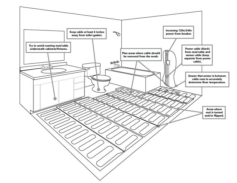
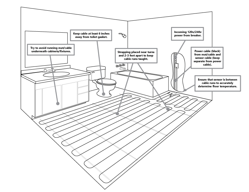
The HEATWAVE Mat/Cable systems are engineered to achieve specific heat output for the square footage to which they are designed. Cutting the red cable to fit a space is extremely dangerous and can result in a fire. Do not cut the red cable to avoid an obstacle or fixture, use other methods as described in this manual. Make sure to avoid damaging/cutting the red cable during/after the installation of the flooring material by being aware of all red cable locations.

1.3 Remember to Measure Resistance

The resistance between the two conductor wires should be measured. Compare this resistance reading to the “Total Ohms” column in Product section 4.1 for Heatwave® Mats, and section 4.2 for Heatwave® Cables. The value should be within ±10%. Also measure the resistance between each of the two conductors and the shielding/ground wire. Both should read infinity or open. If there is a different than expected readings for any of these measurements are observed, contact Heatizon Systems at 888-239-1232. Please refer to Section 7 (Commissioning) for instructions on how to measure the resistance.

Important: measure the resistance four times during the installation process. Remember to always measure, verify and record the actual resistance throughout the installation process (out of the box, after installation, after covering with cementitious material, and after installation of floor covering).

DO NOT Power on the Heatwave® mat/cable until it is fully embedded in a cementious material and that material has completely dried.

1.4 Limited Lifetime Warranty

For the life of the floor covering and while in possession of the original owner, Heatizon warrants that the Heatwave® heating cable is free from defects in material, design and workmanship. The warranty is only valid if the warranty certificate has been properly completed, and the installation is in accordance with the installation instructions.


Jump to Section

Planning The Installation

Before laying the Heatwave® Cable or Mat Floor Warming System, review the installation layout and verify that all dimensions match the need of the project. The installation plan should include the following:

  1. Placement, direction, and dimensions of the Heatwave® Cable or Mat.
  2. The starting and ending points of each Heating Cable length or Mat size.
  3. The location of the thermostat or other suitable activation.
  4. The location of the floor sensor between two heating cables.

REMEMBER! The installation plan* for each area should be retained and be provided to the building owner when the installation is complete.

*It is recommended that photographs be taken to document the installation of the layout.

Installation Considerations

DO:

  1. Completely inspect the Heatwave® System immediately upon its arrival and report any damage to Heatizon Systems and the delivery party.
  2. Clean the floor of all debris before placing the mat/cable on the floor.
  3. Make sure there are no protruding objects (nails, staples, etc.) on the subfloor that could damage the heating element.
  4. Walk over the unprotected Cable/Mat with rubber soled shoes.
  5. Measure and record Cable/Mat resistance according to the instructions.
  6. Use Cables/Mats connected to the same controller or used in the same room or area, that have the same heat output. i.e. ALL Cables/Mats should be EITHER 10 watts/sq. ft. OR ALL 15 watts/sq. ft.
  7. Make sure all components of the system are rated for the same Voltage (120V OR 240V).
  8. Have all electrical work completed by a professional electrician in accordance with all local and national codes and regulations.
  9. Call our Technical Support Hot line at 888-239-1232, for answers to installation questions, help solving a problem, or believe that the Heatwave® system was cut or damaged during installation.

DON’T

  1. DON’T cut the red heating wire.
  2. DON’T POWER ON the Heatwave® system until COMPLETELY EMBEDDED in cementious material
  3. DON’T drop or bang any tools (i.e. trowel) on or hit the heating wires with any sharp objects.
  4. DON’T install any fasteners such as nails, screws, etc. through any area covered by the Heatwave® Cable/Mat.
  5. DON’T shorten the spacing in the Mat.
  6. DON’T install Heatwave® under cabinets, built-in appliances, etc. to avoid excessive heat from building up in those areas.
  7. DON’T install Cables/Mats over expansion joints.
  8. DON’T install Heatwave® in walls.
  9. DON’T overlap Cables/Mats or allow any wires to cross or touch each other.
  10. DON’T crimp the heating wire while customizing the mat
  11. DON’T place high/thick insulating objects over the heated area to avoid excessive build-up of heat in these areas.
  12. DON’T forget to install the floor sensor.
  13. DON’T attempt to repair cut or damaged heating wire without contacting Heatizon Systems first 888-239-1232.
  14. DON’T install the Heatwave® system within 6” of a wax toilet gasket.

Important Safeguards and Warnings

WARNING: Shock and fire hazard

  • If the Heatwave® System is damaged or not installed properly, fire or shock could occur resulting in serious personal injuries or damage to property. Carefully follow the warnings and instructions contained in this manual.
  • It is important that this equipment is installed only by qualified persons who are familiar with the proper sizing, installation, construction and operation of floor warming systems and the hazards involved.
  • The installation must comply with all national and local electrical codes. Consult the authority in the jurisdiction familiar with these requirements, either the NEC (National Electric Code), CSA (Canadian Standard Association) should there be any questions.
  • The Heatwave® System is designed for under floor heating purposes only. Be sure that the floor is not penetrated by nails, screws, or similar devices that can cause damage during and after installation or during subsequent or future floor work.
  • If the Heatwave® System is damaged, it must be replaced or repaired. To repair or to splice any part of the system, use only Heatizon Heatwave® Repair Kit (part number HWRPKIT).

Jump to Section

General Information


The instructions in this manual must be followed when preparing and installing the Heatwave® Cable or Mat Floor Warming System. This manual and the installation layout should be made available to all contractors and installers working on the job. Both should then be turned over to the building owner after the installation is complete.

FAILURE TO FOLLOW THE INSTRUCTIONS IN THIS MANUAL MAY VOID THE WARRANTY ON THE FLOOR WARMING SYSTEM.

Temperature and Time Control
For optimal control of the Heatwave® floor warming system, contact a Heatizon Systems
distributor for a variety of floor sensing thermostat options.

Maintenance
The Heatwave® floor warming system has no moving parts and is virtually maintenance-free. The GFCI (Ground Fault Circuit Interrupter), internal to the thermostat if Heatizon Systems supplied it, should be tested monthly as described in the manufacturer’s pamphlet to ensure its continued safe operation. If an external GFCI is utilized instead, it should be tested monthly.

Subfloors
Heatwave® may be installed over any well insulated subfloor (i.e. plywood, concrete, or underlayment material) prepared in accordance with the most recent TCA (Tile Council of America) guidelines.

Floor Coverings
Heatwave® will be most effective if installed under rigid floors that are naturally good conductors of heat such as ceramic tile, marble, and other stone floorings. There are additional requirements for applications that utilize different floor coverings. For heating wall-to-wall carpeting, parquet, laminate or engineered wood floors and vinyl or linoleum flooring, a thicker heatsink bed is recommended for floating applications and glued down floor. A 1” to 1.5” spacing is recommended between the heating cable and the surface of the floor.

Insulation
Heatwave® will be most effective and efficient if installed over well-insulated areas. Insulation will minimize heat loss into the subfloor (i.e. concrete slab), allowing the heat to transfer to the surface more quickly.


Jump to a Section

Introduction

Heatizon Systems is glad to offer product phone support for the Heatwave product. It is VERY important to have read this manual first. Please have your resistance test numbers and system model name/number available BEFORE calling for technical support.


DOWNLOAD PDF INSTALL MANUAL (COMPLETE)

The Heatwave® Heating Cable comes in pre-established lengths that have been designed to deliver a specified heat density. Therefore, it is essential that all of the Heatwave® Heating Element contained in the kit be installed. Do not cut or alter the red heating cable in any way.

In order to minimize the risk of damage to the Heatwave® Heating Cable, Heatizon Systems
recommends that the Heatwave® Cable be installed immediately prior to the installation of the cementitious material that goes over it.

Never cross the Heatwave® Heating Cable over itself, the in-floor sensor wire, or any other conductor or wire.

When installing Heatizon Systems products, strict compliance with the National Electrical Code, local Building Codes, and Heatizon’s Installation Manual is essential.

It is highly recommend to take photographs to document the installed Heatwave® for future
reference before installing the flooring.


Jump to a Section