M432 Activator – Wiring Guides
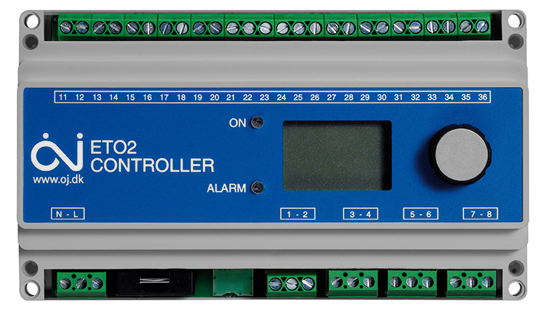
M432(ETO2) Activator/Controller
- Control Unit must be mounted inside or in a water-tight enclosure if mounted outside.
- Control Unit must be located within distance of sensor being used. Sensors can be extended using 6×14-16AWG wire up to 650 feet.
- Wiring/setup for this guide is using one (1) M433/M430 (ETOG) sensor. For other sensor(s) or other situations, please consult the complete user manual.
- Installation/Setup of the activator should be done AFTER completion of installing the SnowMeltz® system and the substrate is fully cured/completed.

The system must not be turned on until the concrete has fully cured.
DO NOT USE SnowMeltz® TO CURE/DRY CONCRETE.
Mounting Sensor Head (M433/M430)
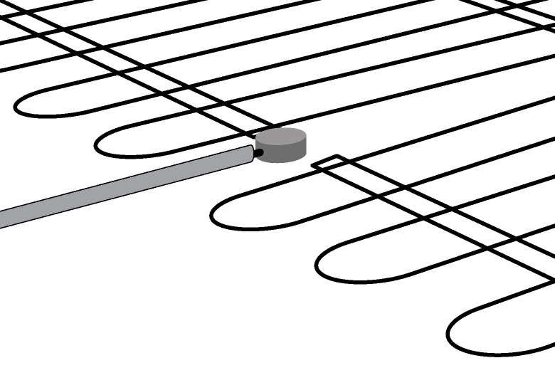
The following must be follower when mounting the in-ground sensor (M433/M430):
- Sensor must be located in the area as the SnowMeltz® system.
- Sensor head must be flush with the top of the asphalt/concrete.
- Space the SnowMeltz® mat slightly to accommodate the sensor head.
- Ensure that heating element does not touch or cross the sensor head, wire, or conduit.
Wiring M432 Power and ETOG Sensor*
- Remove the cover with a small-blade flat head screwdriver by pressing the two slots on the front-center of the cover.
- Mount the unit using the four screw holes on each corner of the unit. Be sure that the mounting location has taken into account:
• Incoming Power
• Proximity to sensor(s) (Extra wiring may be necessary to extend sensor)
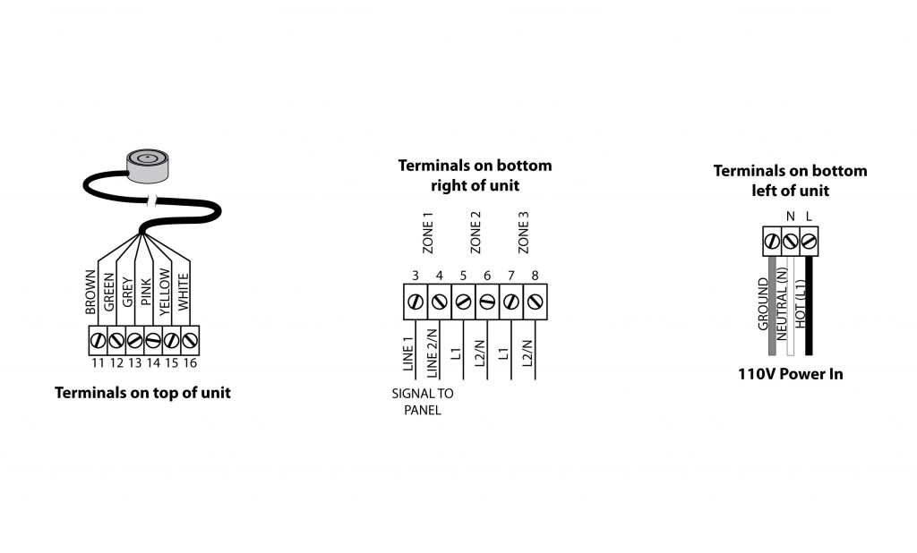
• Proximity to panel and/or heating element - Wire sensor according to diagram in 13.1A.
- Wire connection to panel/heating element using the instructions from the panel and the diagram 13.1B.
- Wire incoming power (110V 15A) following diagram 13.1C.
Once powering on the unit, if the ALARM light blinks at any point during or after setup, check signal and sensor wiring connections.
- Power on the unit and do an initial setup of the software: (using the dial to move the selection up or down and pressing down on the dial to make the selection/ENTER)
• Choose Celsius or Fahrenheit (ENTER)
• Select ETOG (ENTER)*
• Leave “Sensor 2” on the OFF setting (ENTER)
• Leave the “Outdoor Sensor” OFF (ENTER)
• Select “Electric 1-Zone” under APPLICATION (ENTER)
• On this screen, hit (ENTER) to enter the menu, then scroll down to “Setup”
• On the setup menu, scroll down to “Afterrun 1” and hit (ENTER)
• Default for After run is 2 hours, it is advised to adjust this to a longer time period (3-4 hours) and then dial back from there based on the performance of the system. Once complete, hit (ENTER).
• Scroll down to “Exit” and hit (ENTER), the initial setup is complete. - Run an test run of the system to see if everything is working properly.
• To run a test of the system hit (ENTER), scroll down to the “Setup” screen and then select “Force Heat,” hit (ENTER). The internal relay should click on and the panel(s) should activate as well. After both the panel and activator have powered on, with “force Heat” still selected, hit (ENTER) again to deactivate the activator.
- Initial testing in this phase is to check to see if the activator/panel powers on and there are no wiring issues. It is advised to run another activator/panel test or checking settings once snowfall has occurred.
- It is NOT recommended to change the default activation temperature, which should be 37°-38° F
- After testing is completed. The system can be powered off during the non-winter months, but being sure to completely power on the activator and panel(s) before the first snow and leave powered on for the entire season.
- Make any adjustments necessary to activator as required for optimal efficiency for the given
application.
*ETOG is the in-ground sensor, if using additional/different sensors please consult the M432 (ET02) manual for wiring diagrams for these sensors.