Category: Installation Design

SnowMeltz® Expanded Layouts

Laying out SnowMeltz using multiple mats follow the following rules:

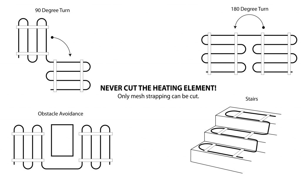
  • SnowMeltz CANNOT overlap any other SnowMeltz cold lead, heating element.
  • Maintain at least 3 inch spacing between mats and cold leads.
  • Spacing mats greater than 5 inches may cause striping (areas of delayed snow/ice melting).
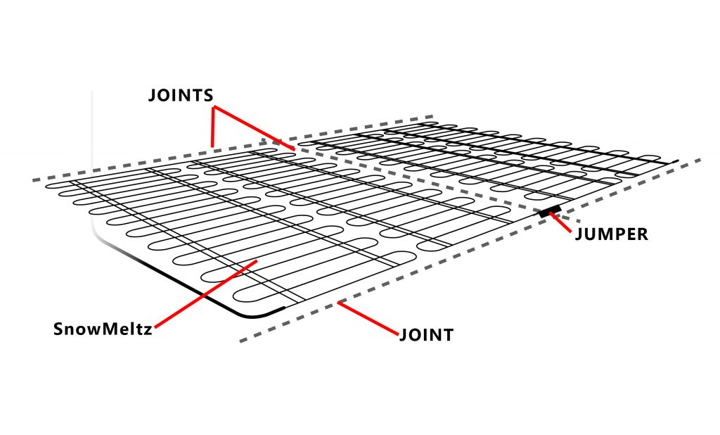
  • Mark all control joint locations before doing layout.
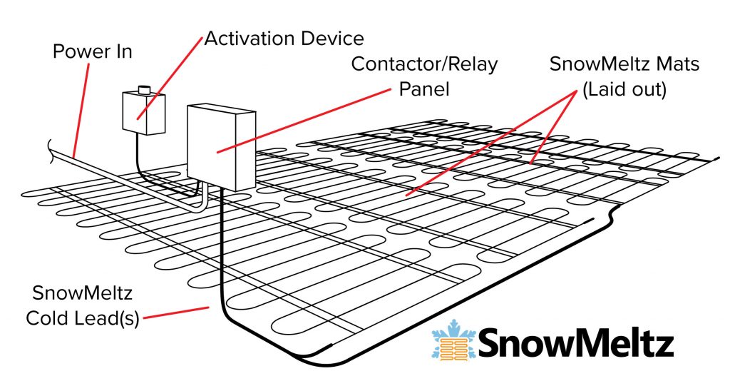
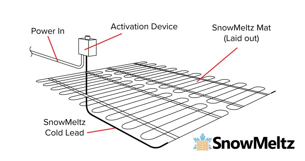
  • Find appropriate location(s) for contactor* and/or activator.
  • Mark tentative location(s) for junction box(es) and activator.
  • Layout mats BEFORE applying the substrate. Do not install them at the same time.
  • Plan layouts with any/all joints in mind in order to minimize crossing those joints.
  • Follow ALL instructions outlined in the primary SnowMeltz instruction manual for installing SnowMeltz mats.

Here are a couple example layouts with the large and jumbo SnowMeltz kits:

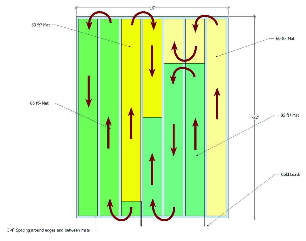
Using the SnowMeltz 290 kit (SM-50W277-37W240-290) to fill a space that is approximately 330 square feet, with 3 inch spacing around the perimeter and between mats. This example has no control joints, therefore no jumpers would be used. All the cold leads would meet the incoming power at the activator device (M326ARS-2Z), where all the electrical connections would be made.

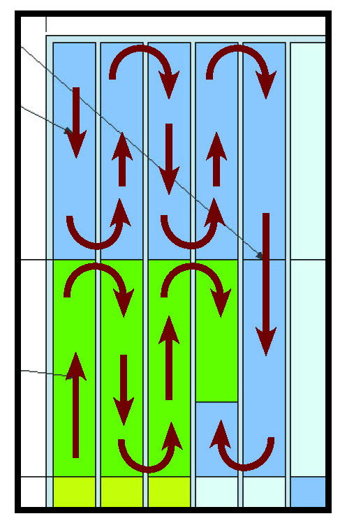
Using the SnowMeltz 820 kit (SM-50W277-37W240-820) to fill a space that is approximately 950 square feet, with 4 inch spacing around the perimeter and between mats. This example has control joints about every 10-11 feet. The mats have been laid out to minimize the number of jumpers required. As you can see, the mats are arranged similarly in four quadrants. See the diagram below for mat routing in each quadrant.

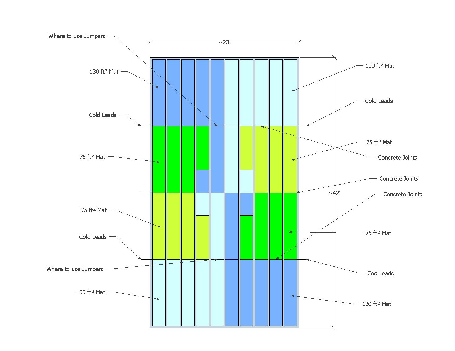
This example would require feeders to each side to junction boxes on either size of the space. These feeder lines should be based on National Electric Code and local codes to carry the appropriate amp load and number of circuits. Any/all junction boxes used should be outdoor-rated.

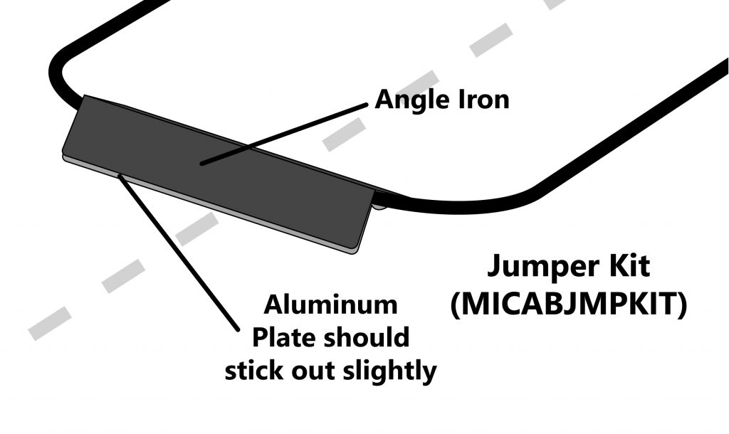
This example uses 1-130 square foot mat and 1-75 square foot mat in each quadrant, with the 130 square foot mat being the one that crosses the horizontal control joint. This is the point where a jumper would be used to protect the SnowMeltz cable from any potential cracking/physical damage. No vertical control joints are needed to be crossed in this example. Be sure to read and follow all installation instructions regarding joints in the primary SnowMeltz manual (SEE: “A Few Concrete Suggestions”).


Jump to a section

SnowMeltz® Installation Design

Gathering Site Information

  • Size and layout of area – Be sure to properly measure the area to be installed to ensure the proper sized SnowMeltz® system has been purchased. Also plan how power will be run to the area and/or met to the cold lead(s).
  • Geographic Location – Depending on the geographic location of the installation area, some adjustments made have to be made during the installation, such as: layout configuration, drainage, heat output, obstacles, etc.
  • Cover or cap material and thickness (1.5” minimum) – SnowMeltz® MUST be embedded in either concrete, asphalt, or sand underneath pavers, ensure the system is at least 1.5 inches from surface.

Determine the Voltage and Amperage

The available supply voltages include 208V, 240V, and 277V.
Ensure based on the voltage and size of system(s) being used,
that there is enough available amperage available.

Important: Operating SnowMeltz® at voltages they are not designed for will damage the system and void the warranty.

Breaker Size
(Amps)
Max Load
(Amps)
5040
4032
3024
2016
1512

Plan the design*

Determine the optimum SnowMeltz® Mat layout for the heated area to ensure coverage. Determine where the cold lead (20 foot) will join to a junction box, panel, or activation device. When installing multiple systems, be sure to plan layout for multiple cold leads being run to the same location. Use included grid (back of the manual) to layout the SnowMeltz® system(s).

  • Make certain to plan for the movement of water created by melted snow.
  • The transition joint between the heating element and the cold lead must be embedded in asphalt, concrete, sand, stone dust, or cementitious material. Do not bend the heating cable within 3” of cold connection.
  • Activation Devices are the eyes and ears of the heating system. Location is important. Please reference installation and operation information in the activation device product literature. Some activation devices may or may not require a different voltage than the heating cable.
  • Consult Heatizon Systems for any other questions.
More than 30 amp SnowMeltz load
Less than 30-amp SnowMeltz load

Jumpers

ASHRAE, NEC, and Heatizon always require the use of jumpers through joints. Never extend the heating cable through any joint in asphalt and/or concrete without a jumper. Determine the number of joints in order to determine the number of Jumper Kits required for the project. Always jumper joints using the appropriate jumper kit provided by Heatizon Systems.

When laying out SnowMeltz® in concrete where jumpers will need to be used, best practice is to minimize the number of times the heating element will cross joints. Ideally, arrange the layout so that the mat fills one section of the concrete (between joints) then crosses the joint(s). The best solution for jumpers is to use the jumper Kit supplied by Heatizon (Heatizon Part #MICABJMPKIT), it includes components for four jumpers.

CONCRETE JOINTS AND USING JUMPERS

Control Joints: Control Joints are intended to control where the slab will crack and are placed either in fresh concrete or saw cut in after the concrete is poured. Spacing of these joints will vary depending on the size and shape of the slab. Use the Cable Jumper to protect the heating cable when crossing control
joints.

Construction Joints: Construction joints are a common result when multiple concrete pours are completed at different stages during construction. Use a Cable Jumper to protect the heating cable when crossing construction joints.

Expansion Joints: Expansion or Isolation joints result when concrete is isolated from something else which can be concrete, a wall, column etc. When an expansion joint is used between two concrete slabs the two structures are not connected using rebar, therefore movement can/will occur between them. Do not cross expansion joints with the heating portion of the cable. The cold lead portion of the cable may cross expansion joints as long as the cold lead is buried under or sleeved with conduit at the bottom of the joint.


Jump to a section