M326 Series Activator – Wiring Guides
M326 Series Mounting
Control Unit must be mounted outside within close proximity of the SnowMeltz® system(s).
- If not using a panel, power should be ran to the location of the M326A/M3262Z.
- If using a panel, the device requires 120V/240V to operate.
- Wiring/setup for this guide is using one (1) M326A/M3262Z, without a panel (switching up to 30 amps). For other installation situations with panels or accessories, please consult the complete user manuals for the M326A/M3262Z and other devices.
- Mounting should be done on top of a sturdy conduit or using the mounting points on the top and bottom to secure it, ensure that nothing obstructs the top sensor from receiving moisture.
- Installation/Setup of the activator should be done AFTER completion of installing the SnowMeltz® system and the substrate is fully cured/completed.
M326 Series Setup
These settings are the same for M326A, M326ARS, M326A2Z & M326ARS2Z series activators.
The following should be performed BEFORE installing the activator and connecting it to power.
- Remove the four screws on the cover.
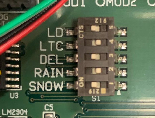
- Look for the five (5) dipswitches near the center of the board.
- The configuration should be as follows, from top to bottom: (Figure 13.2A)
• LD (5) to ON
• LTC (4) to OFF
• DEL (3) to ON
• RAIN (2) to OFF
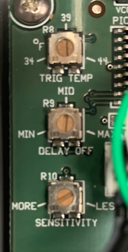
• SNOW (1) to ON - Locate the dials on the left side of the board.
- The configuration should be as follows, from top to bottom: (Figure 13.2B)
• TRIG TEMP to 39
• DELAY OFF to MID
• SENSITIVITY to approximately 2 o’clock (one side should point to MORE) - Replace cover and secure it with the four screws.
- Proceed to wiring the device for use.
The Activator has now been configured to activate the SnowMeltz® mat(s) once the temperature is below 39 AND snow (moisture) is detected. The system will also remain activated for approximately 60-90 minutes AFTER moisture is no longer detected. To change the amount of After Run time, adjust the dial
labeled “DELAY OFF” to MIN or MAX to lessen or lengthen the After Run time.
The following mounting/wiring instructions assume that a relay panel is NOT being used and power is coming from a single 240 volt circuit. For all other installation instances, please consult the complete installation manuals for the M326A and panels for other installation/wiring instructions.
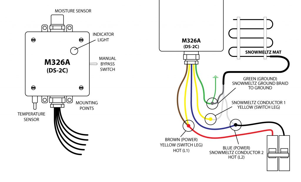
M326A Series Wiring
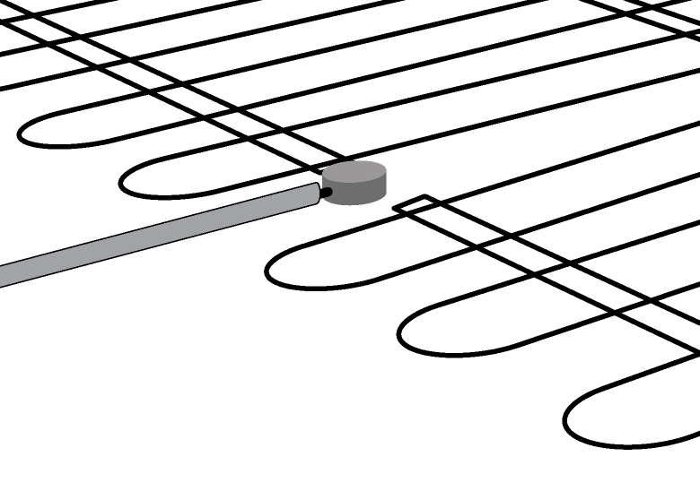
- Choose a location that will receive the same snowfall as the SnowMeltz® system(s) and that will not be obstructed.
- Best practice is to mount the M326A on top of a weather-proof junction box to make the connections to power and the SnowMeltz® mat(s).
- Be sure to follow local code for the correct gauge of wire for a dual-pole 30 amp 240v circuit.
- Power to the M326A must be off before wiring the unit.
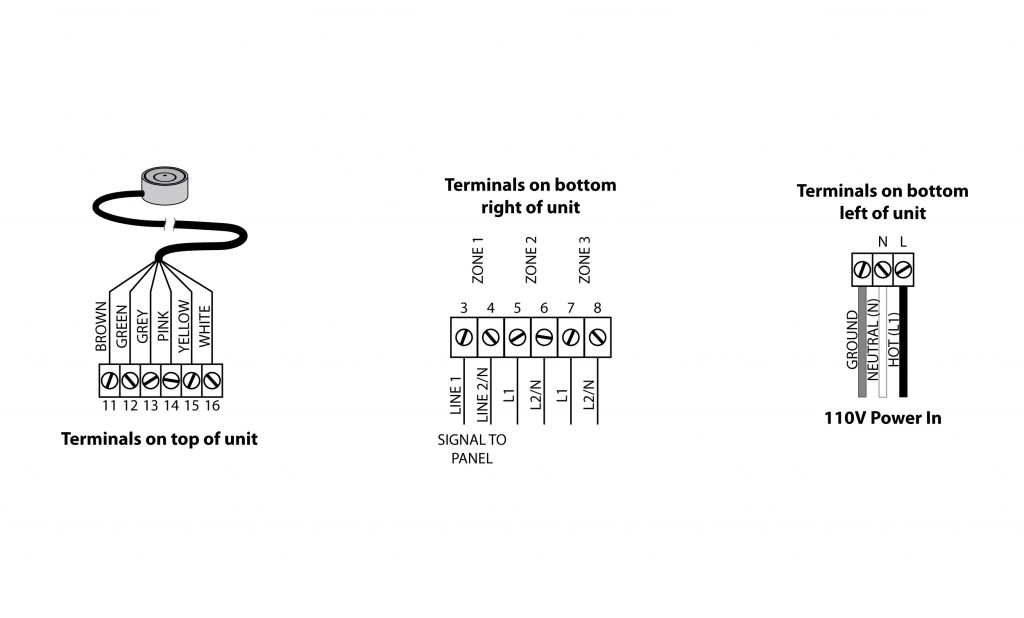
- Wire the green ground wire from the M326A to the silver ground shield from the SnowMeltz® mat and to suitable grounded wire.
- Take one yellow wire and the brown wire and attach them to one leg of the incoming circuit from the breaker.
- The other yellow wire from the M326A will be wired to one of the copper conductors on the SnowMeltz® mat.
- The blue wire and wire it to the other leg of the incoming power and the other copper conductor from the SnowMeltz® mat.
- Ensure all connections are tight and secure and close the junction box and power up the system.
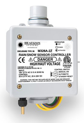
- The light on the front of the M326A should be solid green, indicating power is being supplied to the unit.
- Test the system to switch the power to MANUAL using the switch on the side of the M326A, the status light should be blinking, indicating the M326A is providing power to the SnowMeltz® mat.
- Return the switch to AUTOMATIC, the installation is now complete.
This test is to ensure that the activator powers on correctly and there are no wiring issues. Running another test or checking settings once snowfall has occurred is advisable.