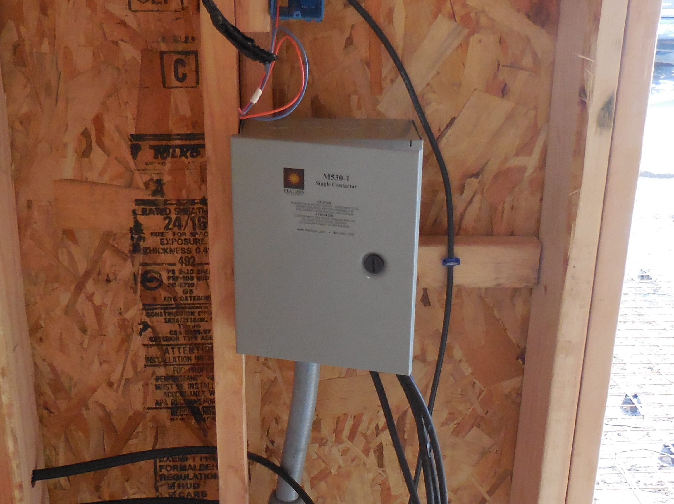
Install Contactor/Relay Panel
The M330/M530 panel must be located inside, unless a custom outdoor-rated enclosure is used. The
location should be free from moisture and reasonably close access to heated area and main
circuit panel for making electrical connections.
When installing multiple SnowMeltz and the total amp load is over 30 amps, a panel will be
required. Heatizon has several options to meet this need:
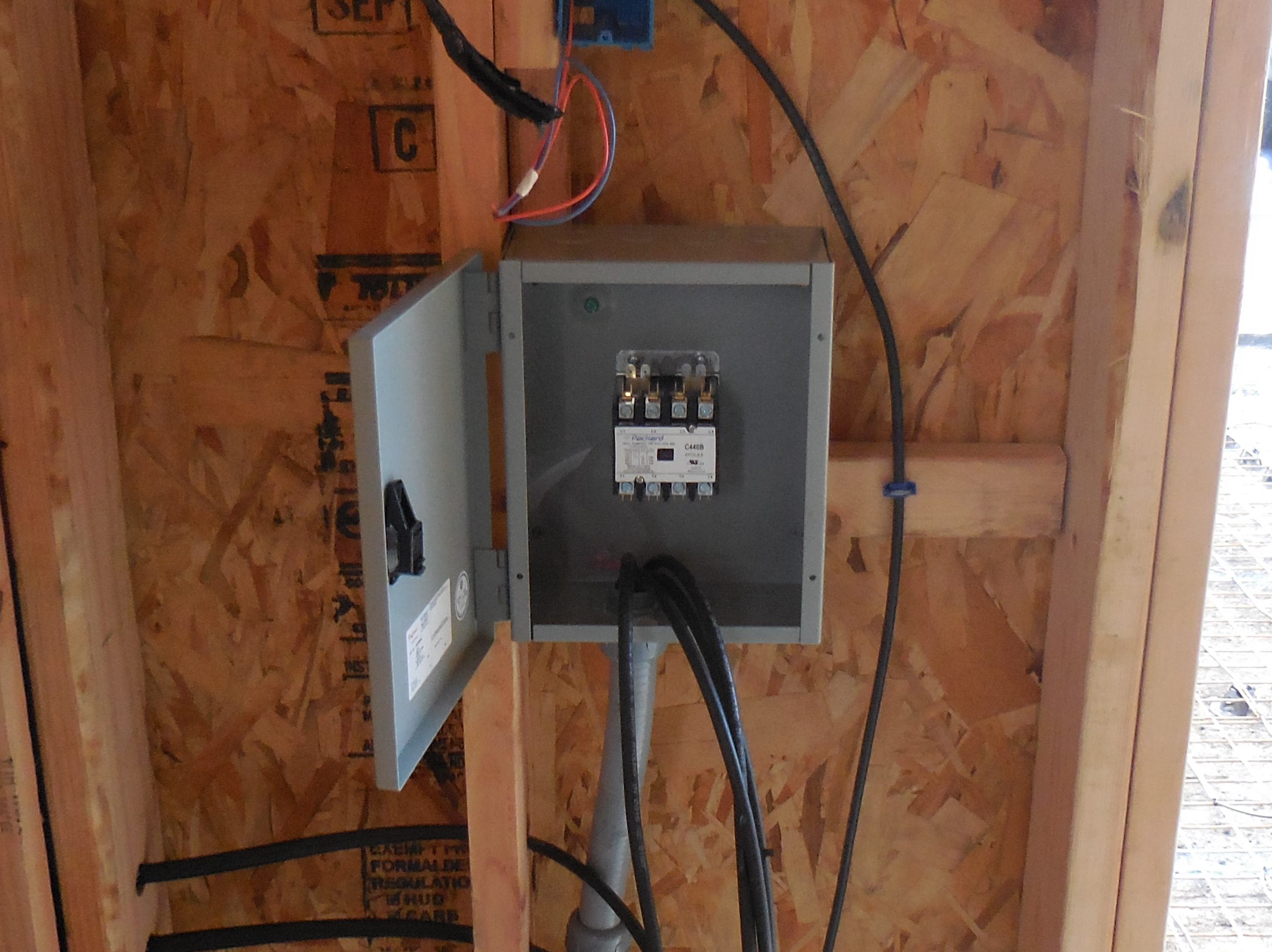
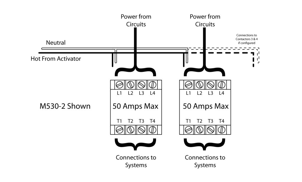
- M530 Series – Contactor panel, perfect for low-budget applications, handles up to 4 circuits, and up to 50 amps per circuit, no GFEP.
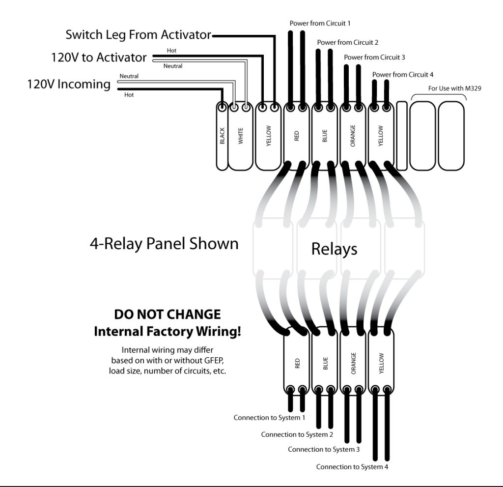
- M330 Series – Relay panel without GFEP, handles up to 4 circuits, and up to 30 amps per circuit.
- M330-50 Series – Relay panel without GFEP, handles up to 4 circuits, and up to 50 amps per circuit.
- M330G Series – Relay panel with GFEP, handles up to 4 circuits, and up to 30 amps per circuit.
- M330G-40 Series – Relay panel with GFEP, handles up to 4 circuits, and up to 40 amps per circuit.
- Custom Panels created to project specifications.
For wiring the panel for your project consult the wiring diagram for that specific panel. Some panels may
or may not require 120V for direct power.
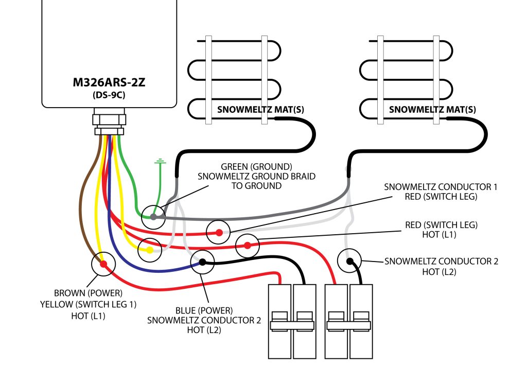
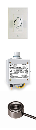
For M530 series contactor panels:
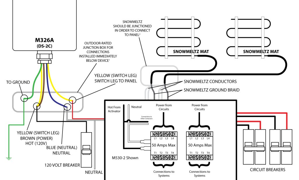
Notes:
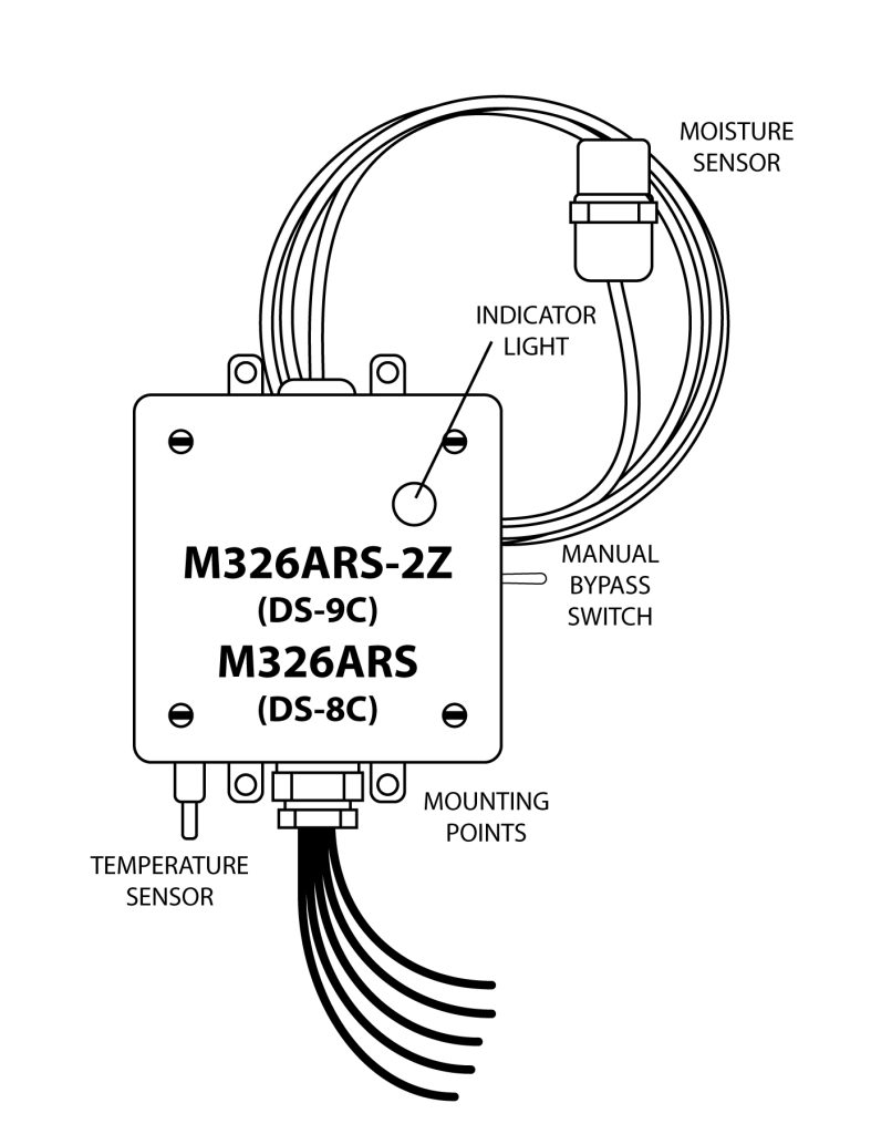
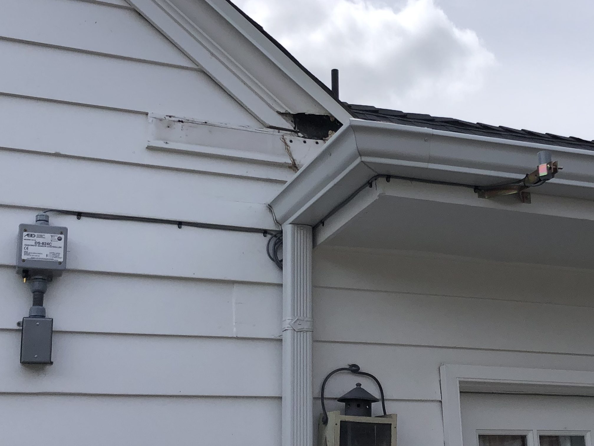
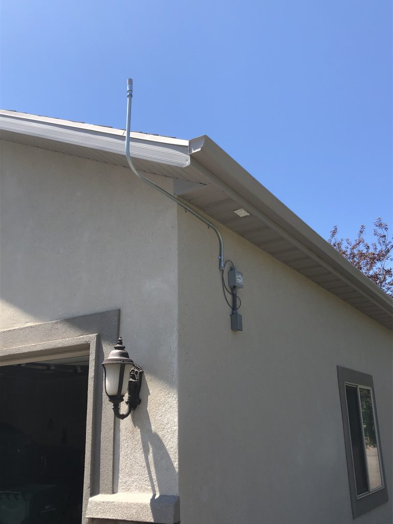
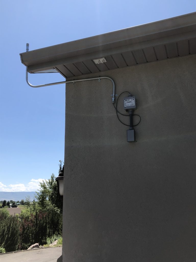
- Connections to the M326 series activators, CANNOT be made inside the device, they MUST be made in a outdoor-rated junction box mounted below the device. Failure to do so will void the warranty and damage the unit.
- SnowMeltz cold leads are 20 feet long, in the event that the cold lead(s) are not long enough, they must be extended using an appropriate gauge wire for the load/voltage and the appropriate junction box dependent on the location of the box. Please follow local codes for type/gauge of wire and type/rating of junction box to be used.
- Use the appropriate number and size of breakers for the project, do not overload circuit breakers, or contactors in a panel.
- Contactors have a maximum capacity of 50 full load amps, do not exceed this rating.
For M330 series relay panels:
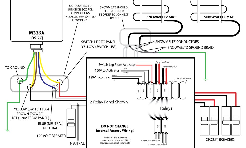
- Connections to the M326 series activators, CANNOT be made inside the device, they MUST be made in a outdoor-rated junction box mounted below the device. Failure to do so will void the warranty and damage the unit.
- SnowMeltz cold leads are 20 feet long, in the event that the cold lead(s) are not long enough, they must be extended using an appropriate gauge wire for the load/voltage and the appropriate junction box dependent on the location of the box. Please follow local codes for type/gauge of wire and type/rating of junction box to be used.
- Use the appropriate number and size of breakers for the project, do not overload circuit breakers or relays in a panel.
- Consult the instructions for the specific relay panel purchased for it’s full load specifications. DO NOT exceed this full load rating.
- Do not alter, tamper with, or change the factory wiring of any M330 Series relay panel, as this will void the warranty and can cause damage to the panel, connected heating systems, and circuit breakers.