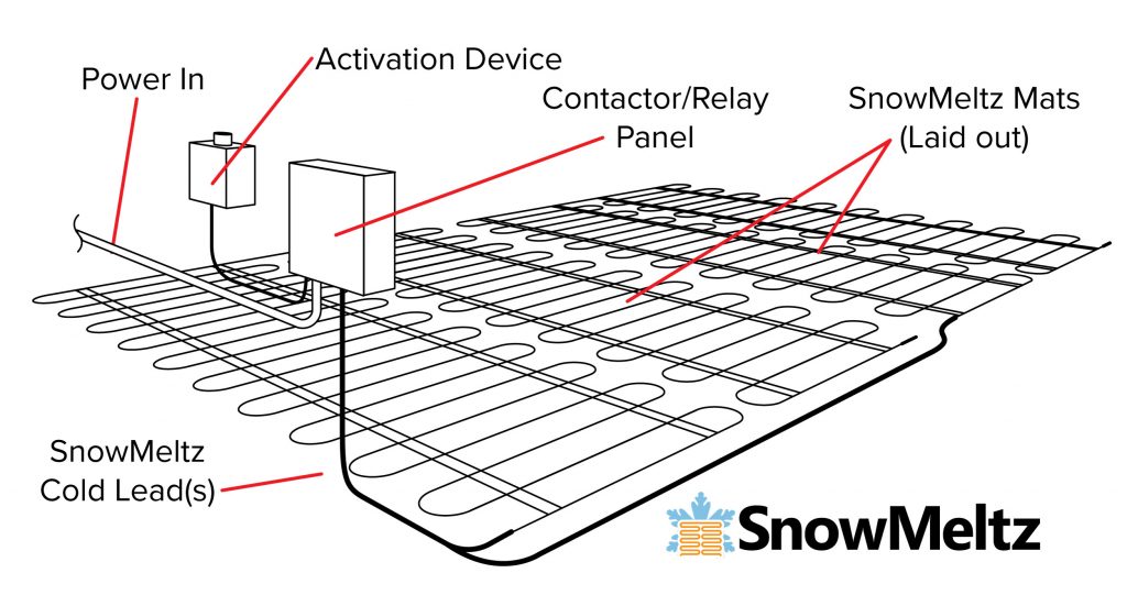
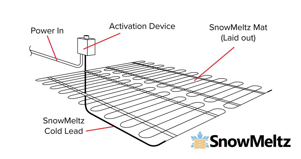
Install Activation Device
Heatizon activation devices come with data sheets, wiring diagrams, and instructions. Install the selected activator by carefully following the specific set of instructions that were included with the activation device. Some systems are professionally designed and can include custom wiring diagrams from our industry professionals. There are three available types of activators that are suitable for SnowMeltz®:
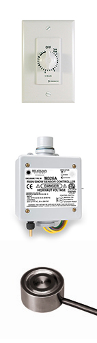
- MANUAL – Manual activators usually consist of a timer switch that keeps the system on for a set amount of time, then powers off the system. This activator requires some sort of panel (regardless of the number of circuits) to switch the load.
- AERIAL – These activators are mounted on a wall or on a conduit in the air in very close proximity to the area to be heated. They can be equipped with temperature and/or moisture sensors, and usually have some form of basic manual override. Depending on the model, it may be able to switch smaller loads (30 amps) without the use of a panel. The sensor for this device must be able to detect the same circumstances that will be present in the area where the SnowMeltz® is installed.
- REMOTE/IN-GROUND – The activators usually have a head unit located indoors and have more functionality and have optional in-ground sensors that detect moisture/temperature on on the concrete/asphalt. These units can also have separate remote temperature sensors. Normally these units require a panel to switch the load. When using in-ground sensors, the conduit for the sensor wire and head unit must NOT cross or come in contact with the heating element. The sensor must be mounted in the SAME substrate as the SnowMeltz® system is installed into. When using a remote temperature sensor, it should be located to receive the same conditions as the heated area.
It is imperative that any/all conduit being used (for sensors, cold leads, power, etc.) do NOT come in contact with the heating element. Consult the individual instructions for the appropriate activator for wiring/mounting. Quick start/Wiring Diagrams for the most popular Heatizon activation devices are included on pages 20-23.
- If the selected activation device requires conduit for a temperature sensor, the conduit must be centered between two runs of heating cable. Always run high voltage and low voltage conductors in separate conduits.
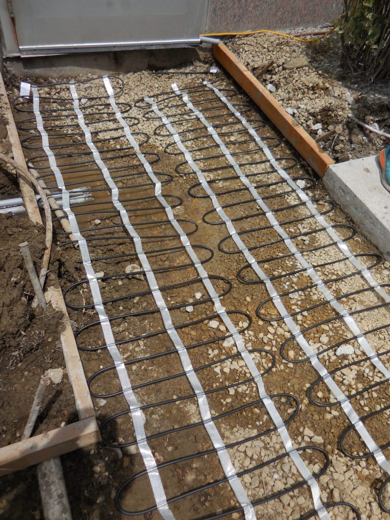
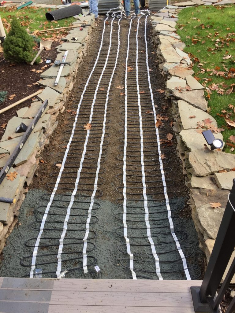
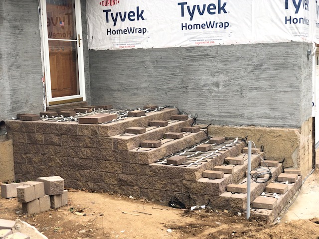
- Heatizon recommends that photographs of the installed heating cable be taken and/or hand drawings documenting the layout be completed prior to installing the final surface.