SnowMeltz Forms
Troubleshooting
Warranty Information
SnowMeltz Forms
Fill out and return the Heatwave Registration form or download and print the layout grid to help layout the Heatwave system.
Fill out and return the Heatwave Registration form or download and print the layout grid to help layout the Heatwave system.
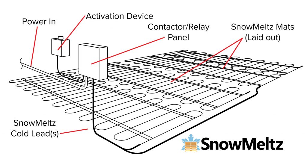
Control Unit must be mounted outside within close proximity of the SnowMeltz® system(s).
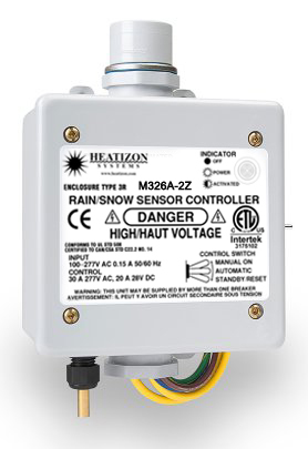
These settings are the same for M326A, M326ARS, M326A2Z & M326ARS2Z series activators.
The following should be performed BEFORE installing the activator and connecting it to power.
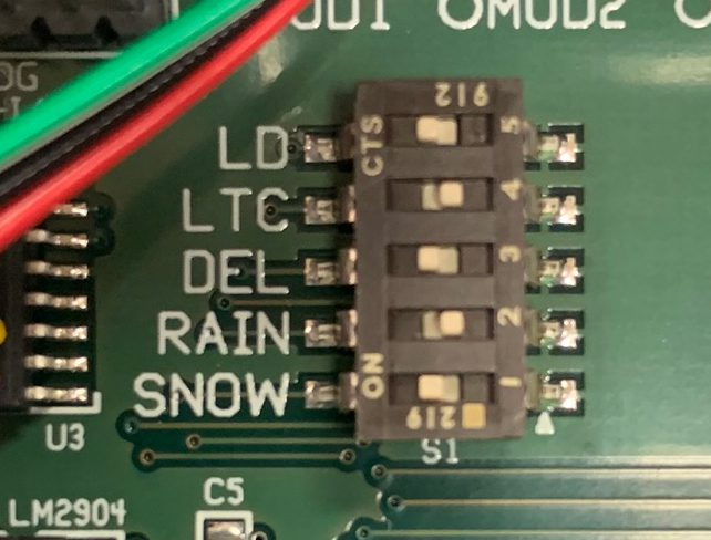
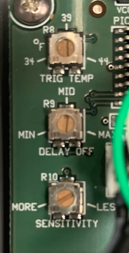
The Activator has now been configured to activate the SnowMeltz® mat(s) once the temperature is below 39 AND snow (moisture) is detected. The system will also remain activated for approximately 60-90 minutes AFTER moisture is no longer detected. To change the amount of After Run time, adjust the dial
labeled “DELAY OFF” to MIN or MAX to lessen or lengthen the After Run time.
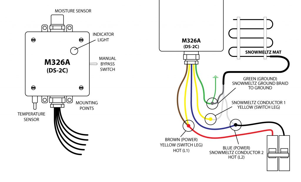
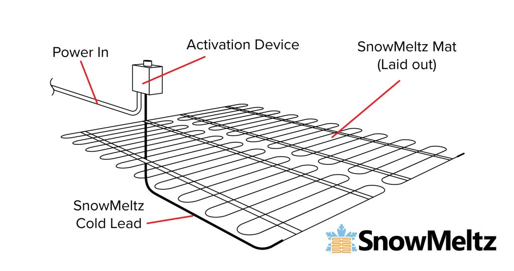
The following mounting/wiring instructions assume that a relay panel is NOT being used and power is coming from a single 240 volt circuit. For all other installation instances, please consult the complete installation manuals for the M326A and panels for other installation/wiring instructions.
This test is to ensure that the activator powers on correctly and there are no wiring issues. Running another test or checking settings once snowfall has occurred is advisable.


The system must not be turned on until the concrete has fully cured.
DO NOT USE SnowMeltz® TO CURE/DRY CONCRETE.
The following must be follower when mounting the in-ground sensor (M433/M430):
Once powering on the unit, if the ALARM light blinks at any point during or after setup, check signal and sensor wiring connections.
*ETOG is the in-ground sensor, if using additional/different sensors please consult the M432 (ET02) manual for wiring diagrams for these sensors.
The connection of the power supply and the activation device must be done by a qualified electrician in accordance with the National Electrical Code (NEC) and the Canadian Electrical Code (CEC). Refer to the wiring diagram included with the activation device and/or panel(s).
120 or 277 VAC — Single Phase
208, 240, or 480 VAC — Two Phase
The grounding shield from the Cold Lead(s) must be wired to Ground for all primary power installations. Section 426 of the NEC requires that each circuit to the heating cable be protected with a ground fault equipment protection devices.
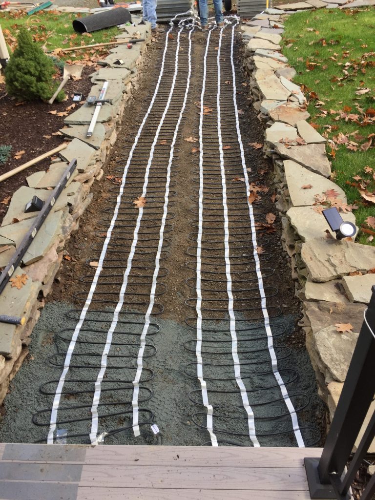
Heatizon recommends that photographs of the installed heating cable be taken and/or hand drawings documenting the layout be completed prior to before installing the asphalt, concrete, pavers, stone or tile.
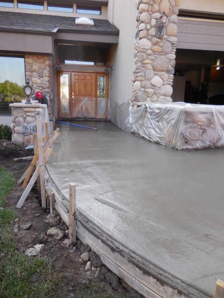
Proceed with applying concrete. Ensure that the concrete covers the entire heating element and the connection between the heating cable and cold leads. Great care should be taken to not damage the heating cables by impacting, cutting or other abuse.
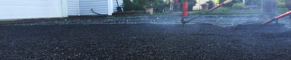
Heatizon Systems heating cable is of high quality and durable construction. As a result, it can tolerate the heat and compression of newly poured asphalt with some modification. The heating cables can tolerate 464°F(240°C) for 30 minutes. For single pour asphalt, cover the heating element with 1/2” of substrate material prior to installing asphalt per the directions below. For both single and two pour asphalt installations place a layer of asphalt at least 1/2 inch thick over the cables by hand, and roll with a roller of approximately 1.5 ton size. This will protect the heating cables from damage by tools or paving equipment and will protect the cable from heat during placement of the main pour. Continuously check the insulation resistance of the heating cables to verify that the cables are not damaged during placement of the asphalt. Continue with the main pour.
Proceed with the installation by covering the heating cable with a layer of sand or stone dust. Ensure that the sand or stone dust covers the entire heating element and the connection between the heating element and cold leads before the pavers are installed. Great care should be taken to not damage the heating cables by impacting, cutting or other abuse.
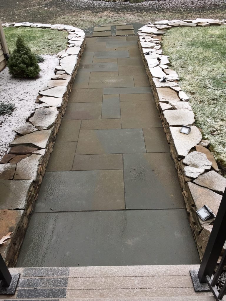
Cover the heating cable with mortar to completely embed them and allow it to set. Allowing the first layer of mortar to set will protect the heating cables during the final installation and the setting bed for stone or tile. Install the Stone or Tile and keep note that the final cable depth of the cable from the surface should be 2”. Great care should be taken to not damage the heating cables by impacting, cutting or other abuse.
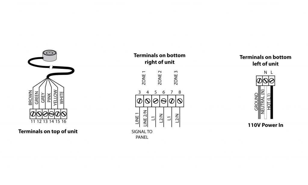
Heatizon activation devices come with data sheets, wiring diagrams, and instructions. Install the selected activator by carefully following the specific set of instructions that were included with the activation device. Some systems are professionally designed and can include custom wiring diagrams from our industry professionals. There are three available types of activators that are suitable for SnowMeltz®:
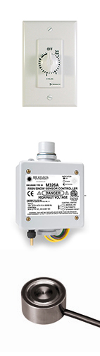
It is imperative that any/all conduit being used (for sensors, cold leads, power, etc.) do NOT come in contact with the heating element. Consult the individual instructions for the appropriate activator for wiring/mounting. Quick start/Wiring Diagrams for the most popular Heatizon activation devices are included on pages 20-23.
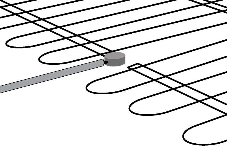
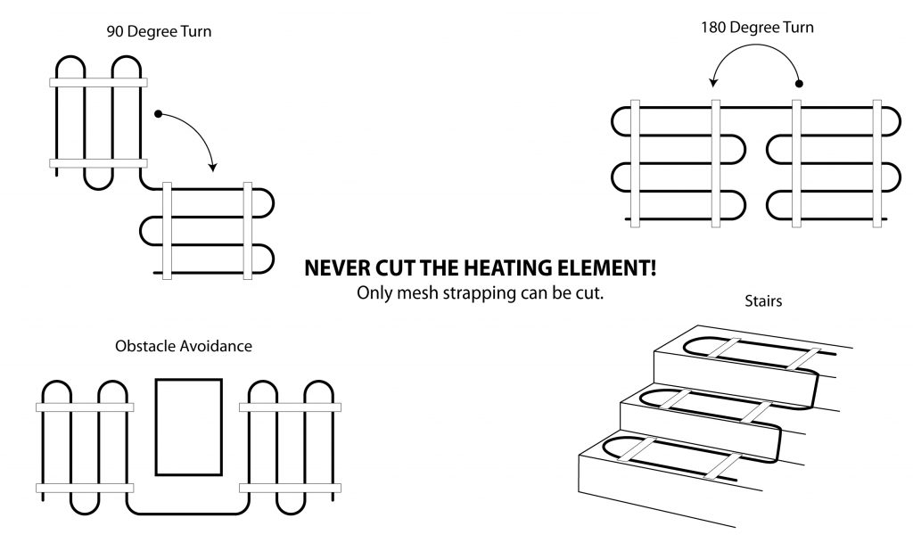
Loose heating cable not in a mat may be secured in place by landscape stakes and plastic wire ties, welded wire fabric and plastic wire ties or tape, or pre-punched steel straps purchased from your Heatizon Distributor or Representative. Do not compress or strain the cable, run heavy machinery, equipment, or vehicles over it. Be careful to avoid stepping on the cold section factory connection of the cable. Consult the NEC or CEC for grounding requirements of rebar or welded wire fabric for concrete installations. When working with concrete or asphalt joints, design the layout so each section of the slab is covered and the cable crossing of joints are minimized. See page 15 for example layouts. Mats should be installed in evenly spaced runs per the system design and plan. Sleeve hand rail posts to avoid drilling or penetrations in the slab after the pour.
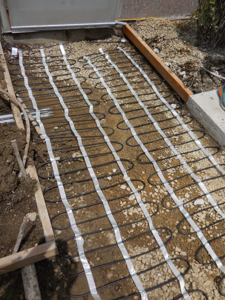
Loose heating cable not in mat form may be secured in place by landscape stakes and plastic wire ties, welded wire fabric and plastic wire ties or tape, or pre-punched steel straps purchased from your Heatizon Distributor or Representative. Cables in a mat can be layed out in the configuration desired directly on the surface. Do not compress or strain the cable, run heavy machinery, equipment, or vehicles over it. Be careful to avoid stepping on the cold section factory connection of the cable. Consult the NEC or CEC for grounding requirements of rebar or welded wire fabric for asphalt installations. When working with concrete or asphalt joints, design the layout so each section of the slab is covered and the cable crossing of joints are minimized. See page 9 for example layouts. Cables or mats should be installed in evenly spaced runs per the system design and plan. Sleeve hand rail posts to avoid drilling or penetrations in the slab after the pour.
The heating cable may be secured in place by landscape stakes and plastic wire ties, welded wire fabric and plastic wire ties or tape. Do not compress or strain the cable. Do not run heavy machinery, equipment, or vehicles over the cable. Be careful to avoid stepping on the cold section factory connection of the cable.
The heating cable may be secured in place with pre-punched steel straps or anchor kits purchased from your Heatizon Distributor or Representative. Do not compress or strain the cable. Do not run heavy machinery, equipment, or vehicles over it. Be careful to avoid stepping on the cold section factory connection of the cable.
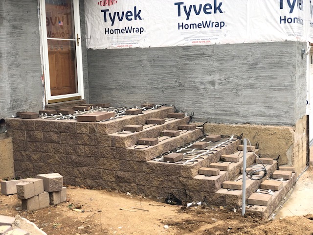
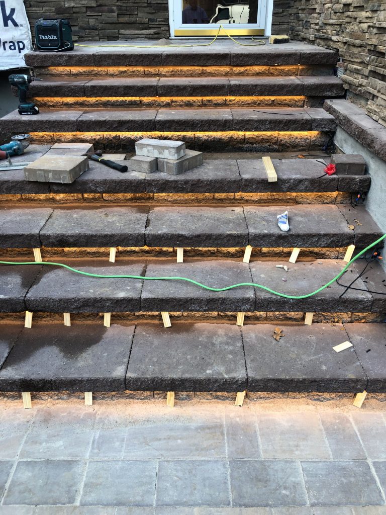
When installing in stairs, ensure that the heating element should not be too close to the edge of the stair and still be completely embedded. Also be sure that where the cable spans the rise of the stairs get embedded in the substrate to avoid causing a hot spot, and damaging the cable. Avoid doing a full run on the rise of the stair.
The cold lead(s) should be run in a conduit to either a junction box, panel, or activator and should NEVER cross or come in contact with the SnowMeltz® heating element.
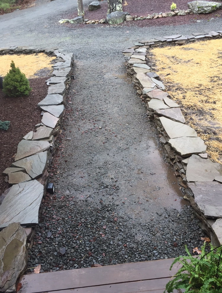
Ensure that the substrate has been properly compacted and drainage has been satisfactorily addressed. For substrate preparation and concrete recommendations please refer to page 1 of this manual for “A FEW CONCRETE SUGGESTIONS”. Other site preparation recommendations include, cleaning up the site to eliminate objects that may damage the heating element prior to, during and after the installation.
Use the site sketch to transfer the following information to the site.
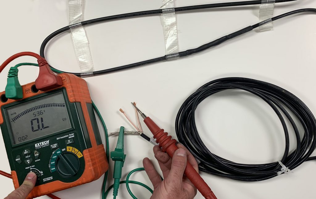
Before, during, and after installation, it is necessary to measure the insulation resistance between the heating conductor and the protective grounding screen with a 500VDC Megohmmeter. This measured value may not be less than 0.5 Megohms. Connect the voltage lead to the inner cold lead conductors and the earth lead to the cold lead outer grounding braid or sheath. Test resistance at 500VDC. Record the measured values in the certificate of warranty.
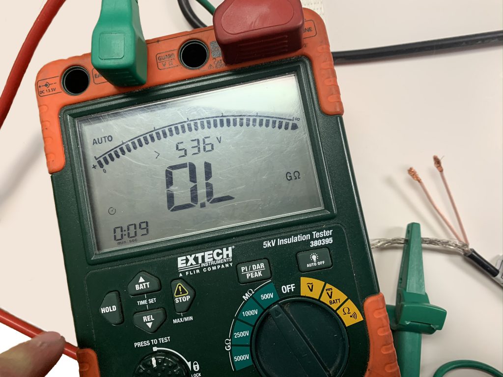
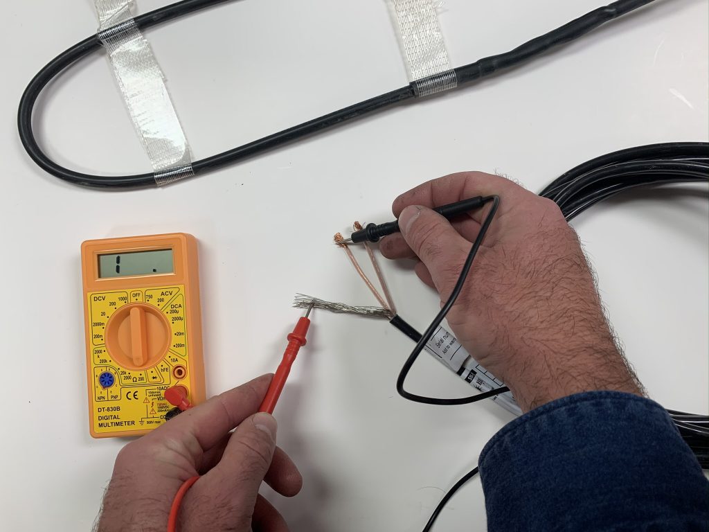
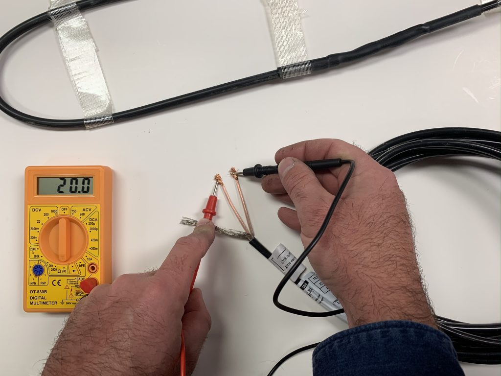
Before, during, and after installation, it is necessary to measure the resistance of the heating circuit with a multimeter. The measured values should be equal -5% to +10%.
Connect one meter lead to the one cold lead inner conductor and the other meter lead to the other cold lead inner conductor. Take the Ohm reading. Record the measured values in the certificate of warranty.
Be sure to check product label for proper resistance, operating amperage, operating voltage, cable length and other important information when performing tests.
The available supply voltages include 208V, 240V, and 277V.
Ensure based on the voltage and size of system(s) being used,
that there is enough available amperage available.
Important: Operating SnowMeltz® at voltages they are not designed for will damage the system and void the warranty.
| Breaker Size (Amps) | Max Load (Amps) |
|---|---|
| 50 | 40 |
| 40 | 32 |
| 30 | 24 |
| 20 | 16 |
| 15 | 12 |
Determine the optimum SnowMeltz® Mat layout for the heated area to ensure coverage. Determine where the cold lead (20 foot) will join to a junction box, panel, or activation device. When installing multiple systems, be sure to plan layout for multiple cold leads being run to the same location. Use included grid (back of the manual) to layout the SnowMeltz® system(s).
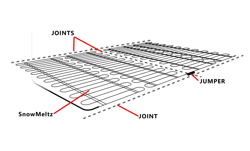
ASHRAE, NEC, and Heatizon always require the use of jumpers through joints. Never extend the heating cable through any joint in asphalt and/or concrete without a jumper. Determine the number of joints in order to determine the number of Jumper Kits required for the project. Always jumper joints using the appropriate jumper kit provided by Heatizon Systems.
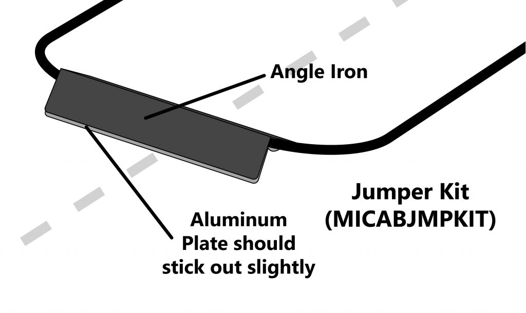
When laying out SnowMeltz® in concrete where jumpers will need to be used, best practice is to minimize the number of times the heating element will cross joints. Ideally, arrange the layout so that the mat fills one section of the concrete (between joints) then crosses the joint(s). The best solution for jumpers is to use the jumper Kit supplied by Heatizon (Heatizon Part #MICABJMPKIT), it includes components for four jumpers.
Control Joints: Control Joints are intended to control where the slab will crack and are placed either in fresh concrete or saw cut in after the concrete is poured. Spacing of these joints will vary depending on the size and shape of the slab. Use the Cable Jumper to protect the heating cable when crossing control
joints.
Construction Joints: Construction joints are a common result when multiple concrete pours are completed at different stages during construction. Use a Cable Jumper to protect the heating cable when crossing construction joints.
Expansion Joints: Expansion or Isolation joints result when concrete is isolated from something else which can be concrete, a wall, column etc. When an expansion joint is used between two concrete slabs the two structures are not connected using rebar, therefore movement can/will occur between them. Do not cross expansion joints with the heating portion of the cable. The cold lead portion of the cable may cross expansion joints as long as the cold lead is buried under or sleeved with conduit at the bottom of the joint.