Blog

Product Selection – Complete Kits

Since SnowMeltz CANNOT be shortened, it is vital to choose the correct size system before installing. It is advisable to always get a smaller system for the area, for example: if the area is 48 square feet, choose a 40 or 45 square foot system.

SnowMeltz® Mat Kits – 37 Watts/Ft2 @240VAC

Standard SnowMeltz kits include the SnowMeltz mat(s), an automatic activator, and jumpers. These kits are designed to use a single 20, 30 or 40 amp, 240 volt GFI breaker.

Heatizon Part NumberCircuit
Size
Coverage
Area/Square
Foot
Mat(s)
Dimensions
SM-50W277-37W240-1020102’x5′
SM-50W277-37W240-1520152’x8′
SM-50W277-37W240-2020202’x10′
SM-50W277-37W240-2520252’x13′
SM-50W277-37W240-3520352’x17′
SM-50W277-37W240-4020402’x20′
SM-50W277-37W240-4520452’x23′
SM-50W277-37W240-5020502’x25′
SM-50W277-37W240-6020602’x30′
SM-50W277-37W240-7520752’x37′
SM-50W277-37W240-8520852’x43′
SM-50W277-37W240-100201002’x50′
SM-50W277-37W240-110*301102’x25′; 2’x30′
SM-50W277-37W240-120*301202’x30′; 2’x30′
SM-50W277-37W240-130301302’x65′
SM-50W277-37W240-135*301352’x30′; 2’x37′
SM-50W277-37W240-145*301452’x30′; 2’x43′
SM-50W277-37W240-150*301502’x37′; 2’x37′
SM-50W277-37W240-160*401602’x37′; 2’x43′
SM-50W277-37W240-170*401702’x43′; 2’x43′
SM-50W277-37W240-185*401852’x43′; 2’x50′

* These kits contain two or more SnowMeltz mats to reach the stated square footage.

SnowMeltz® Large Mat Kits – 37 Watts/Ft2 @240VAC

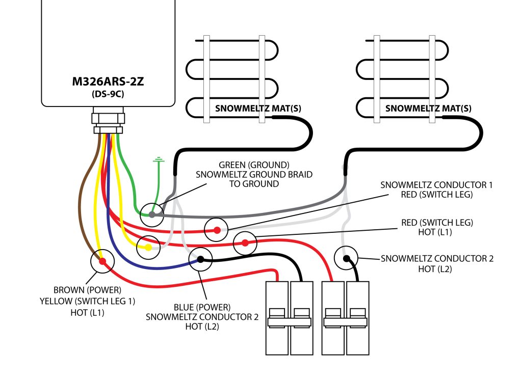
Large SnowMeltz kits include the SnowMeltz mat(s), a dual-circuit automatic activator, and jumpers. These kits are designed to use two 20, 30 or 40 amp, 240 volt GFI breakers.

Heatizon Part NumberCircuit
Size
Coverage
Area/Square
Foot
Mat(s)
Dimensions
SM-50W277-37W240-2002×20200(2)-2’x50′
SM-50W277-37W240-2202×30220(2)-2’x25′; (2)-2’x30′
SM-50W277-37W240-2402×30240(4)-2’x30′
SM-50W277-37W240-2702×30270(2)-2’x30′; (2)-2×37′
SM-50W277-37W240-2902×30290(2)-2’x30′; (2)-2’x43′
SM-50W277-37W240-3002×30300(4)-2’x37′
SM-50W277-37W240-3202×40320(2)-2’x37′; (2)-2’x43′
SM-50W277-37W240-3402×40340(4)-2’x43′
SM-50W277-37W240-3702×40370(2)-2’x43′; (2)-2×50′
SM-50W277-37W240-3802×40380(2)-2’x30′; (2)-2×65′

SnowMeltz® Jumbo Mat Kits – 37 Watts/Ft2 @240VAC

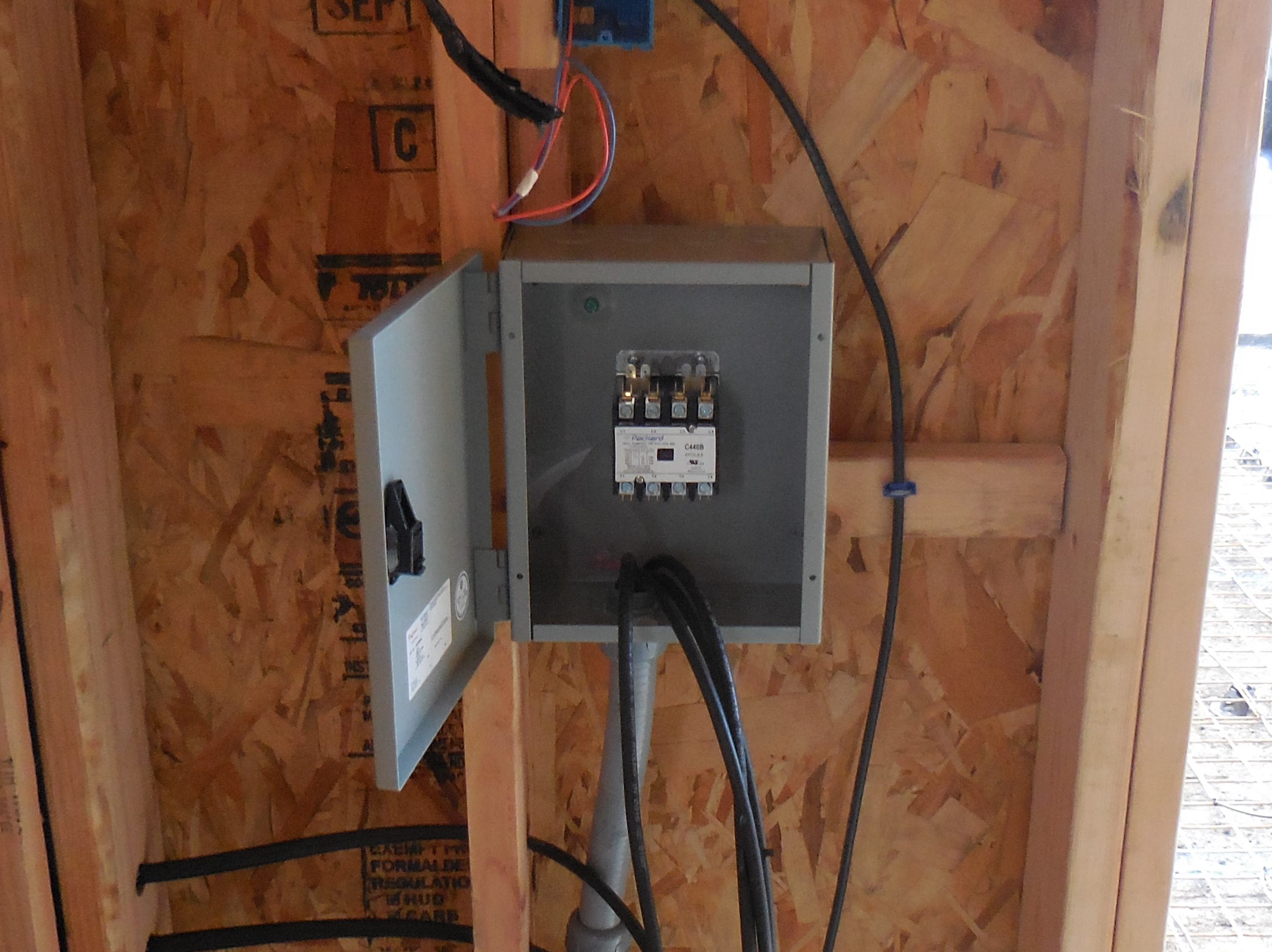
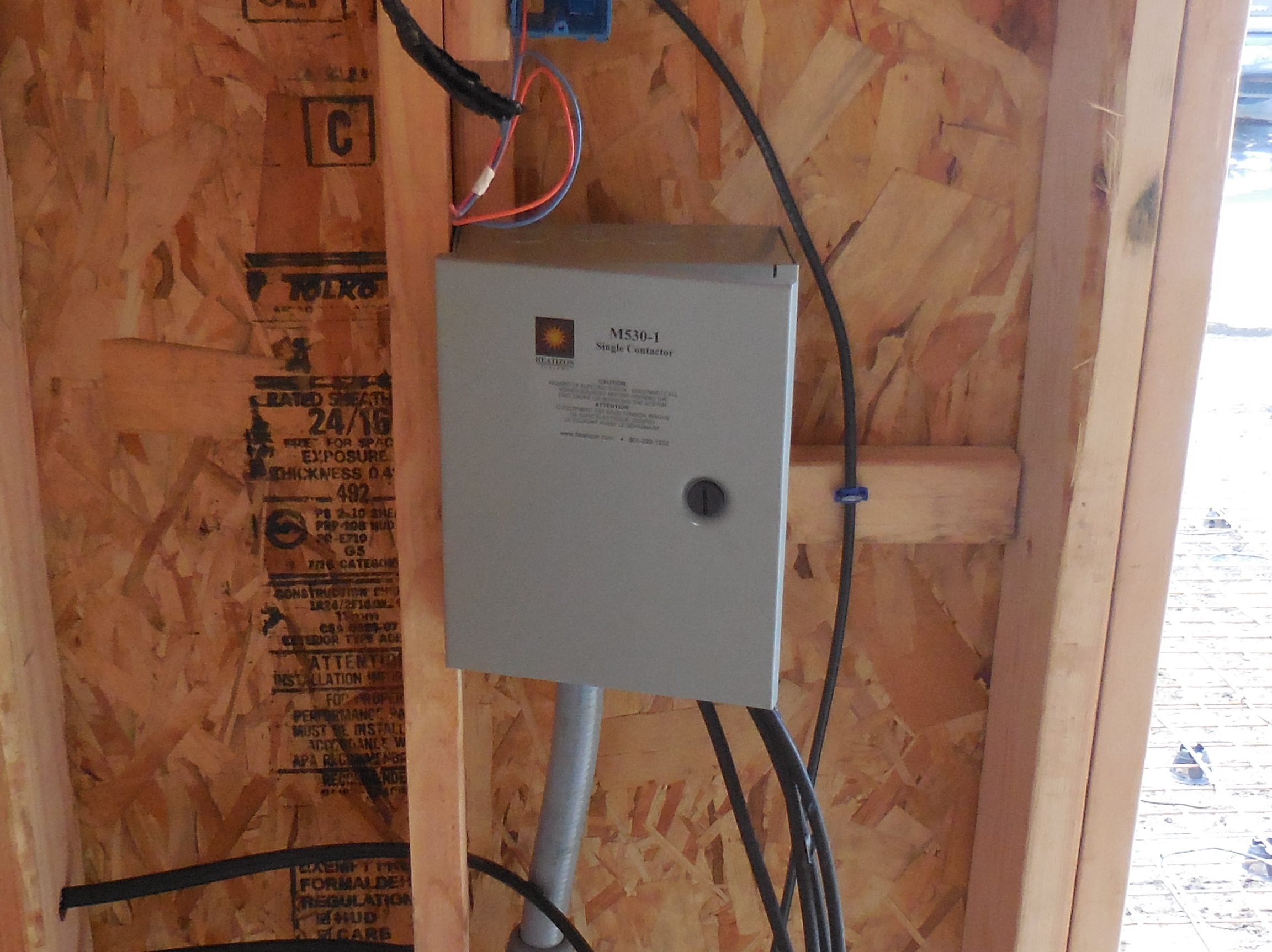
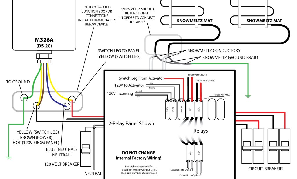
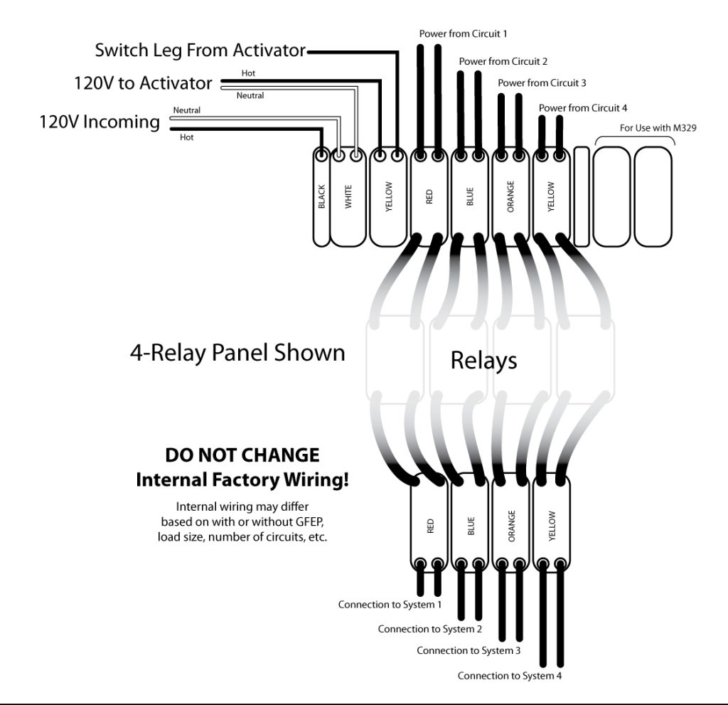
Jumbo SnowMeltz kits include the SnowMeltz mat(s), an automatic activator, contactor panel, and jumpers. These kits are designed to use two, three or four 40/50 amp, 240 volt GFI breakers.

Heatizon Part NumberCircuit
Size
Coverage
Area/Square
Foot
Mat(s)
Dimensions
SM-50W277-37W240-4102×40410(2)-2’x37′; (2)-2×65′
SM-50W277-37W240-6153×40615(3)-2’x37′; (3)-2×65′
SM-50W277-37W240-8204×40820(4)-2’x30′; (4)-2’x65′
SM-50W277-37W240-10404×501040(8)-2’x30′

Jump to a section

Install Contactor/Relay Panel

The M330/M530 panel must be located inside, unless a custom outdoor-rated enclosure is used. The
location should be free from moisture and reasonably close access to heated area and main
circuit panel for making electrical connections.

DSCN1033-edited Install Contactor/Relay Panel
DSCN1034-edited Install Contactor/Relay Panel

When installing multiple SnowMeltz and the total amp load is over 30 amps, a panel will be
required. Heatizon has several options to meet this need:

  • M530 Series – Contactor panel, perfect for low-budget applications, handles up to 4 circuits, and up to 50 amps per circuit, no GFEP.
  • M330 Series – Relay panel without GFEP, handles up to 4 circuits, and up to 30 amps per circuit.
  • M330-50 Series – Relay panel without GFEP, handles up to 4 circuits, and up to 50 amps per circuit.
  • M330G Series – Relay panel with GFEP, handles up to 4 circuits, and up to 30 amps per circuit.
  • M330G-40 Series – Relay panel with GFEP, handles up to 4 circuits, and up to 40 amps per circuit.
  • Custom Panels created to project specifications.

For wiring the panel for your project consult the wiring diagram for that specific panel. Some panels may
or may not require 120V for direct power.

For M530 series contactor panels:

Snowmeltz-M326A-M530-1024x618 Install Contactor/Relay Panel

Notes:

contactor-wiring-1024x618 Install Contactor/Relay Panel
  • Connections to the M326 series activators, CANNOT be made inside the device, they MUST be made in a outdoor-rated junction box mounted below the device. Failure to do so will void the warranty and damage the unit.
  • SnowMeltz cold leads are 20 feet long, in the event that the cold lead(s) are not long enough, they must be extended using an appropriate gauge wire for the load/voltage and the appropriate junction box dependent on the location of the box. Please follow local codes for type/gauge of wire and type/rating of junction box to be used.
  • Use the appropriate number and size of breakers for the project, do not overload circuit breakers, or contactors in a panel.
  • Contactors have a maximum capacity of 50 full load amps, do not exceed this rating.

For M330 series relay panels:

Snowmeltz-M326A-M330-1024x618 Install Contactor/Relay Panel
relay-wiring-e1655759436825-1024x991 Install Contactor/Relay Panel
  • Connections to the M326 series activators, CANNOT be made inside the device, they MUST be made in a outdoor-rated junction box mounted below the device. Failure to do so will void the warranty and damage the unit.
  • SnowMeltz cold leads are 20 feet long, in the event that the cold lead(s) are not long enough, they must be extended using an appropriate gauge wire for the load/voltage and the appropriate junction box dependent on the location of the box. Please follow local codes for type/gauge of wire and type/rating of junction box to be used.
  • Use the appropriate number and size of breakers for the project, do not overload circuit breakers or relays in a panel.
  • Consult the instructions for the specific relay panel purchased for it’s full load specifications. DO NOT exceed this full load rating.
  • Do not alter, tamper with, or change the factory wiring of any M330 Series relay panel, as this will void the warranty and can cause damage to the panel, connected heating systems, and circuit breakers.

Jump to a section

M326ARS-2Z Activation Device

Snowmeltz-m326ars-787x1024 M326ARS-2Z Activation Device

The M326ARS/M326ARS-2Z is an automatic temperature and moisture sensor that switches up to 30 amps (M326ARS) and up to two 30 amp loads (M326ARS-2Z). Both have a remote moisture sensor that can be located in a location up to 10 feet away from the main unit, providing for better moisture gathering placement.

For wiring the M326ARS, please refer to the primary SnowMeltz Manual wiring diagram for the M326A as wiring for both units is the same.

Wiring the M326ARS-2Z using two circuits is as follows:

SnowMeltz-m326ar2z-wiring-1024x742 M326ARS-2Z Activation Device
warning-sign M326ARS-2Z Activation Device

Important: DO NOT OVERLOAD CIRCUITS Connect SnowMeltz mats in proper way to ensure adequate load balancing.

M326ARS/M326ARS-2Z Location

IMG_8177-edited-1 M326ARS-2Z Activation Device

The M326ARS/M326ARS-2Z must be located outside for accurate temperature/moisture reading. The main unit can be mounted on an exterior wall or to a post, provided that all necessary electrical connections can be made. The moisture sensor should be located in such a way that it receives the same
exposure to falling moisture as the area being controlled. The sensor head can be located up to 10 feet
away from the main M326ARS/M326ARS-2Z unit.

From the pictures, you can see the main unit and remote sensor are mounted in separate locations
in order to maximize moisture detection.

IMG_6980-768x1024 M326ARS-2Z Activation Device
IMG_6979-768x1024 M326ARS-2Z Activation Device

Jump to a section

SnowMeltz® Expanded Layouts

Laying out SnowMeltz using multiple mats follow the following rules:

  • SnowMeltz CANNOT overlap any other SnowMeltz cold lead, heating element.
  • Maintain at least 3 inch spacing between mats and cold leads.
  • Spacing mats greater than 5 inches may cause striping (areas of delayed snow/ice melting).
  • Mark all control joint locations before doing layout.
  • Find appropriate location(s) for contactor* and/or activator.
  • Mark tentative location(s) for junction box(es) and activator.
  • Layout mats BEFORE applying the substrate. Do not install them at the same time.
  • Plan layouts with any/all joints in mind in order to minimize crossing those joints.
  • Follow ALL instructions outlined in the primary SnowMeltz instruction manual for installing SnowMeltz mats.

Here are a couple example layouts with the large and jumbo SnowMeltz kits:

SnowMeltz_layout_Page_09-1024x807 SnowMeltz® Expanded Layouts

Using the SnowMeltz 290 kit (SM-50W277-37W240-290) to fill a space that is approximately 330 square feet, with 3 inch spacing around the perimeter and between mats. This example has no control joints, therefore no jumpers would be used. All the cold leads would meet the incoming power at the activator device (M326ARS-2Z), where all the electrical connections would be made.

Using the SnowMeltz 820 kit (SM-50W277-37W240-820) to fill a space that is approximately 950 square feet, with 4 inch spacing around the perimeter and between mats. This example has control joints about every 10-11 feet. The mats have been laid out to minimize the number of jumpers required. As you can see, the mats are arranged similarly in four quadrants. See the diagram below for mat routing in each quadrant.

SM-layouts-820-kit-edited SnowMeltz® Expanded Layouts

This example would require feeders to each side to junction boxes on either size of the space. These feeder lines should be based on National Electric Code and local codes to carry the appropriate amp load and number of circuits. Any/all junction boxes used should be outdoor-rated.

This example uses 1-130 square foot mat and 1-75 square foot mat in each quadrant, with the 130 square foot mat being the one that crosses the horizontal control joint. This is the point where a jumper would be used to protect the SnowMeltz cable from any potential cracking/physical damage. No vertical control joints are needed to be crossed in this example. Be sure to read and follow all installation instructions regarding joints in the primary SnowMeltz manual (SEE: “A Few Concrete Suggestions”).

SnowMeltz_layout_Page_10 SnowMeltz® Expanded Layouts

Jump to a section

Circuit Design – Expanded Kits

SnowMeltz Expanded System Circuit Design

In order to ensure proper load balancing on circuits, the SnowMeltz expanded kits have been designed to use combinations of mats on specific circuits:

SnowMeltz® Large Mat Kits

Heatizon Part Number Circuit
Number/
Amperage
Mats Amps Per
Mat @ 240V
Amps Per
Circuit @ 240V
Mat(s) Square Footage Mat
Dimensions
SM-50W277-37W240-200 1 – 20A SM-50W277-37W240-100 15 15 100 2’x50′
2 – 20A SM-50W277-37W240-100 15 15 100 2’x50′
SM-50W277-37W240-220 1- 30A SM-50W277-37W240-50 7.7 17 50 2’x25′
SM-50W277-37W240-60 9.3 60 2’x30′
2 – 30A SM-50W277-37W240-50 7.7 17 50 2’x25′
SM-50W277-37W240-60 9.3 60 2’x30′
SM-50W277-37W240-240 1- 30A SM-50W277-37W240-60(x2) 9.3 19 60 2’x30′
2- 30A SM-50W277-37W240-60(x2) 9.3 19 60 2’x30′
SM-50W277-37W240-270 1- 30A SM-50W277-37W240-60 9.3 21 60 2’x30′
SM-50W277-37W240-75 11.6 75 2’x37′
2- 30A SM-50W277-37W240-60 9.3 21 60 2’x30′
SM-50W277-37W240-75 11.6 75 2’x37′
SM-50W277-37W240-290 1 – 30A SM-50W277-37W240-60 9.3 22 60 2’x30′
  SM-50W277-37W240-85 13.1 85 2’x43′
2 – 30A SM-50W277-37W240-60 9.3 22 60 2’x30′
  SM-50W277-37W240-85 13.1 85 2’x43′
SM-50W277-37W240-300 1 – 30A SM-50W277-37W240-75(x2) 11.6 23 75 2’x37′
2 – 30A SM-50W277-37W240-75(x2) 11.6 23 75 2’x37′
SM-50W277-37W240-320 1 – 40A SM-50W277-37W240-75 11.6 25 75 2’x43′
SM-50W277-37W240-85 13.1 85 2’x50′
2 – 40A SM-50W277-37W240-75 11.6 25 75 2’x43′
SM-50W277-37W240-85 13.1 85 2’x50′
SM-50W277-37W240-340 1 – 40A SM-50W277-37W240-85(x2) 13.1 26 85 2’x43′
2 – 40A SM-50W277-37W240-85(x2) 13.1 26 85 2’x43′
SM-50W277-37W240-370 1 – 40A SM-50W277-37W240-85 13.1 29 85 2’x43′
SM-50W277-37W240-100 15.4 100 2’x50′
2 – 40A SM-50W277-37W240-85 13.1 29 85 2’x43′
SM-50W277-37W240-100 15.4 100 2’x50′
SM-50W277-37W240-380 1 – 40A SM-50W277-37W240-60 9.3 30 60 2’x30′
SM-50W277-37W240-130 20 130 2’x65′
2 – 40A SM-50W277-37W240-60 9.3 30 60 2’x30′
SM-50W277-37W240-130 20 130 2’x65′

SnowMeltz® Jumbo Mat Kits

Heatizon Part Number Circuit
Number/
Amperage
Mats Amps Per
Mat @ 240V
Amps Per
Circuit @ 240V
Mat(s) Square Footage Mat
Dimensions
SM-50W277-37W240-410 1 – 40A SM-50W277-37W240-75 11.6 32 75 2’x37′
SM-50W277-37W240-130 20 130 2’x65′
2 – 40A SM-50W277-37W240-75 11.6 32 75 2’x37′
SM-50W277-37W240-130 20 130 2’x65′
SM-50W277-37W240-615 1- 40A SM-50W277-37W240-75 11.6 32 75 2’x37′
SM-50W277-37W240-130 20 130 2’x65′
2- 40A SM-50W277-37W240-75 11.6 32 75 2’x37′
SM-50W277-37W240-130 20 130 2’x65′
3- 40A SM-50W277-37W240-75 11.6 32 75 2’x37′
SM-50W277-37W240-130 20 130 2’x65′
SM-50W277-37W240-820 1 – 40A SM-50W277-37W240-75 11.6 32 75 2’x37′
SM-50W277-37W240-130 20 130 2’x65′
2 – 40A SM-50W277-37W240-75 11.6 32 75 2’x37′
SM-50W277-37W240-130 20 130 2’x65′
3 – 40A SM-50W277-37W240-75 11.6 32 75 2’x37′
SM-50W277-37W240-130 20 130 2’x65′
4 – 40A SM-50W277-37W240-75 11.6 32 75 2’x37′
SM-50W277-37W240-130 20 130 2’x65′
SM-50W277-37W240-1040 1 – 50A SM-50W277-37W240-130 20 40 75 2’x65′
SM-50W277-37W240-130 20 130 2’x65′
2 – 50A SM-50W277-37W240-130 20 40 85 2’x65′
SM-50W277-37W240-130 20 100 2’x65′
3 – 50A SM-50W277-37W240-130 20 40 60 2’x65′
SM-50W277-37W240-130 20 130 2’x65′
4 – 50A SM-50W277-37W240-130 20 40 60 2’x65′
SM-50W277-37W240-130 20 130 2’x65′
warning-sign Circuit Design - Expanded Kits

Important: DO NOT OVERLOAD CIRCUITS!
Follow the load balancing chart to ensure the appropriate loads are on specific
circuits. It is also important to use properly sized breakers to be able to achieve the
desired amount of power required.

When installing SnowMeltz multiple mat systems, be sure to keep track of which mat is going to
the appropriate circuit. Mark the cold leads and/or note resistance to keep track.

The use of junction boxes may be required to extend cold leads back to either the activation
device or to the contactor panel. Extending/junctioning cold leads MUST be done in accordance
with the National Electric Code and any/all local codes. Be sure to note the amps per mat/circuit
in order to determine the appropirate conductor and junction box to use. Any junction box used
outside MUST be outdoor-rated.

Do not make ANY connections inside of the following activators:

  • M326A/2Z
  • M326ARS/2Z

All electrical connections for these devices MUST take place outside of the device, in a
outdoor-rated junction box with adequate space for all connections


Jump to a section

SnowMeltz Forms

Troubleshooting

Warranty Information

SnowMeltz Warranty (PDF)

SnowMeltz Forms

Fill out and return the Heatwave Registration form or download and print the layout grid to help layout the Heatwave system.

Layout Grid

Registration Form

Order from Amazon?
Be sure to leave a review!


Jump to a section

M326 Series Activator – Wiring Guides

M326 Series Mounting

Control Unit must be mounted outside within close proximity of the SnowMeltz® system(s).

m326a-2z-new M326 Series Activator - Wiring Guides
  • If not using a panel, power should be ran to the location of the M326A/M3262Z.
  • If using a panel, the device requires 120V/240V to operate.
  • Wiring/setup for this guide is using one (1) M326A/M3262Z, without a panel (switching up to 30 amps). For other installation situations with panels or accessories, please consult the complete user manuals for the M326A/M3262Z and other devices.
  • Mounting should be done on top of a sturdy conduit or using the mounting points on the top and bottom to secure it, ensure that nothing obstructs the top sensor from receiving moisture.
  • Installation/Setup of the activator should be done AFTER completion of installing the SnowMeltz® system and the substrate is fully cured/completed.

M326 Series Setup

These settings are the same for M326A, M326ARS, M326A2Z & M326ARS2Z series activators.

The following should be performed BEFORE installing the activator and connecting it to power.

  1. Remove the four screws on the cover.
  2. Look for the five (5) dipswitches near the center of the board.
  3. The configuration should be as follows, from top to bottom: (Figure 13.2A)
    • LD (5) to ON
    • LTC (4) to OFF
    • DEL (3) to ON
    • RAIN (2) to OFF
    • SNOW (1) to ON
  4. Locate the dials on the left side of the board.
  5. The configuration should be as follows, from top to bottom: (Figure 13.2B)
    • TRIG TEMP to 39
    • DELAY OFF to MID
    • SENSITIVITY to approximately 2 o’clock (one side should point to MORE)
  6. Replace cover and secure it with the four screws.
  7. Proceed to wiring the device for use.
M326A-switches M326 Series Activator - Wiring Guides
M326A-dials M326 Series Activator - Wiring Guides

The Activator has now been configured to activate the SnowMeltz® mat(s) once the temperature is below 39 AND snow (moisture) is detected. The system will also remain activated for approximately 60-90 minutes AFTER moisture is no longer detected. To change the amount of After Run time, adjust the dial
labeled “DELAY OFF” to MIN or MAX to lessen or lengthen the After Run time.

The following mounting/wiring instructions assume that a relay panel is NOT being used and power is coming from a single 240 volt circuit. For all other installation instances, please consult the complete installation manuals for the M326A and panels for other installation/wiring instructions.

M326A-wiring-1024x618 M326 Series Activator - Wiring Guides

M326A Series Wiring

  1. Choose a location that will receive the same snowfall as the SnowMeltz® system(s) and that will not be obstructed.
  2. Best practice is to mount the M326A on top of a weather-proof junction box to make the connections to power and the SnowMeltz® mat(s).
  3. Be sure to follow local code for the correct gauge of wire for a dual-pole 30 amp 240v circuit.
  4. Power to the M326A must be off before wiring the unit.
  5. Wire the green ground wire from the M326A to the silver ground shield from the SnowMeltz® mat and to suitable grounded wire.
  6. Take one yellow wire and the brown wire and attach them to one leg of the incoming circuit from the breaker.
  7. The other yellow wire from the M326A will be wired to one of the copper conductors on the SnowMeltz® mat.
  8. The blue wire and wire it to the other leg of the incoming power and the other copper conductor from the SnowMeltz® mat.
  9. Ensure all connections are tight and secure and close the junction box and power up the system.
  10. The light on the front of the M326A should be solid green, indicating power is being supplied to the unit.
  11. Test the system to switch the power to MANUAL using the switch on the side of the M326A, the status light should be blinking, indicating the M326A is providing power to the SnowMeltz® mat.
  12. Return the switch to AUTOMATIC, the installation is now complete.

This test is to ensure that the activator powers on correctly and there are no wiring issues. Running another test or checking settings once snowfall has occurred is advisable.

Learn About Other Activators


Jump to a section

M432 Activator – Wiring Guides

M432(ETO2) Activator/Controller

ETO2_F M432 Activator - Wiring Guides
M432(ETO2) With Cover Removed
  • Control Unit must be mounted inside or in a water-tight enclosure if mounted outside.
  • Control Unit must be located within distance of sensor being used. Sensors can be extended using 6×14-16AWG wire up to 650 feet.
  • Wiring/setup for this guide is using one (1) M433/M430 (ETOG) sensor. For other sensor(s) or other situations, please consult the complete user manual.
  • Installation/Setup of the activator should be done AFTER completion of installing the SnowMeltz® system and the substrate is fully cured/completed.
warning-sign M432 Activator - Wiring Guides

The system must not be turned on until the concrete has fully cured.
DO NOT USE SnowMeltz® TO CURE/DRY CONCRETE.

Mounting Sensor Head (M433/M430)

M433-ETOG-1 M432 Activator - Wiring Guides

The following must be follower when mounting the in-ground sensor (M433/M430):

  • Sensor must be located in the area as the SnowMeltz® system.
  • Sensor head must be flush with the top of the asphalt/concrete.
  • Space the SnowMeltz® mat slightly to accommodate the sensor head.
  • Ensure that heating element does not touch or cross the sensor head, wire, or conduit.

Wiring M432 Power and ETOG Sensor*

ETO2-wiring-1024x618 M432 Activator - Wiring Guides
Figures 13.1A, 13.1B, 13.1C
  1. Remove the cover with a small-blade flat head screwdriver by pressing the two slots on the front-center of the cover.
  2. Mount the unit using the four screw holes on each corner of the unit. Be sure that the mounting location has taken into account:
    • Incoming Power
    • Proximity to sensor(s) (Extra wiring may be necessary to extend sensor)
    • Proximity to panel and/or heating element
  3. Wire sensor according to diagram in 13.1A.
  4. Wire connection to panel/heating element using the instructions from the panel and the diagram 13.1B.
  5. Wire incoming power (110V 15A) following diagram 13.1C.
warning-sign M432 Activator - Wiring Guides

Once powering on the unit, if the ALARM light blinks at any point during or after setup, check signal and sensor wiring connections.

  1. Power on the unit and do an initial setup of the software: (using the dial to move the selection up or down and pressing down on the dial to make the selection/ENTER)
    • Choose Celsius or Fahrenheit (ENTER)
    • Select ETOG (ENTER)*
    • Leave “Sensor 2” on the OFF setting (ENTER)
    • Leave the “Outdoor Sensor” OFF (ENTER)
    • Select “Electric 1-Zone” under APPLICATION (ENTER)
    • On this screen, hit (ENTER) to enter the menu, then scroll down to “Setup”
    • On the setup menu, scroll down to “Afterrun 1” and hit (ENTER)
    • Default for After run is 2 hours, it is advised to adjust this to a longer time period (3-4 hours) and then dial back from there based on the performance of the system. Once complete, hit (ENTER).
    • Scroll down to “Exit” and hit (ENTER), the initial setup is complete.
  2. Run an test run of the system to see if everything is working properly.
    • To run a test of the system hit (ENTER), scroll down to the “Setup” screen and then select “Force Heat,” hit (ENTER). The internal relay should click on and the panel(s) should activate as well. After both the panel and activator have powered on, with “force Heat” still selected, hit (ENTER) again to deactivate the activator.
  • Initial testing in this phase is to check to see if the activator/panel powers on and there are no wiring issues. It is advised to run another activator/panel test or checking settings once snowfall has occurred.
  • It is NOT recommended to change the default activation temperature, which should be 37°-38° F
  1. After testing is completed. The system can be powered off during the non-winter months, but being sure to completely power on the activator and panel(s) before the first snow and leave powered on for the entire season.
  2. Make any adjustments necessary to activator as required for optimal efficiency for the given
    application.

*ETOG is the in-ground sensor, if using additional/different sensors please consult the M432 (ET02) manual for wiring diagrams for these sensors.


Jump to a section

Electrical Connections

The connection of the power supply and the activation device must be done by a qualified electrician in accordance with the National Electrical Code (NEC) and the Canadian Electrical Code (CEC). Refer to the wiring diagram included with the activation device and/or panel(s).

Electrical Requirements:

120 or 277 VAC — Single Phase
208, 240, or 480 VAC — Two Phase

The grounding shield from the Cold Lead(s) must be wired to Ground for all primary power installations. Section 426 of the NEC requires that each circuit to the heating cable be protected with a ground fault equipment protection devices.

Expanded SnowMeltz Kits have specific circuit design/load balancing requirements, please see: CIRCUIT DESIGN

Heatizon recommends that photographs of the installed heating cable be taken and/or hand drawings documenting the layout be completed prior to before installing the asphalt, concrete, pavers, stone or tile.


Jump to a section

Surface Application

For Concrete Applications:

DSCN0318-768x1024 Surface Application

Proceed with applying concrete. Ensure that the concrete covers the entire heating element and the connection between the heating cable and cold leads. Great care should be taken to not damage the heating cables by impacting, cutting or other abuse.

For Asphalt Applications:

Heatizon Systems heating cable is of high quality and durable construction. As a result, it can tolerate the heat and compression of newly poured asphalt with some modification. The heating cables can tolerate 464°F(240°C) for 30 minutes. For single pour asphalt, cover the heating element with 1/2” of substrate material prior to installing asphalt per the directions below. For both single and two pour asphalt installations place a layer of asphalt at least 1/2 inch thick over the cables by hand, and roll with a roller of approximately 1.5 ton size. This will protect the heating cables from damage by tools or paving equipment and will protect the cable from heat during placement of the main pour. Continuously check the insulation resistance of the heating cables to verify that the cables are not damaged during placement of the asphalt. Continue with the main pour.

asphalt-smz-1024x211 Surface Application

For Paver Applications:

59337900782__2EC869CF-D793-4C28-8EF0-F7426C8E3E51-e1646235955470-768x1024 Surface Application

Proceed with the installation by covering the heating cable with a layer of sand or stone dust. Ensure that the sand or stone dust covers the entire heating element and the connection between the heating element and cold leads before the pavers are installed. Great care should be taken to not damage the heating cables by impacting, cutting or other abuse.

For Stone or Tile with Mortar Applications:

Cover the heating cable with mortar to completely embed them and allow it to set. Allowing the first layer of mortar to set will protect the heating cables during the final installation and the setting bed for stone or tile. Install the Stone or Tile and keep note that the final cable depth of the cable from the surface should be 2”. Great care should be taken to not damage the heating cables by impacting, cutting or other abuse.


Jump to a section